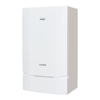
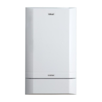
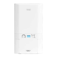
Do you have a question about the IDEAL Evomax 30 and is the answer not in the manual?
Explains the Evomax cascade flue system for connecting boilers via a common flue header.
Details system configurations, including gas type, models, number of boilers, and system capacity.
Lists components included in the Starter Kit for 30-80 and 100-150 models.
Lists components for the Extension Kit to add single boilers to the system.
Describes the purpose and fitting of wire retaining clips to prevent tube connection movement.
Explains how the Cascade Header is suspended and how boiler flue tubes are secured.
Lists relevant standards for flue system construction, installation, and testing.
Advises on planning the flue route for minimal directional changes, recommending one elbow.
Specifies the minimum flue pipe diameter and its relation to flue length.
Recommends selecting flue terminals that minimize resistance and prevent ingress.
Outlines the steps for designing the flue system, from determining heat output to calculating flue length.
Graph showing combustion products flow rate vs. cascade total system capacity.
Table detailing system models, capacities, combustion data, and flue data for cascade systems.
Step-by-step guide to setting the Evomax user interface for Multiline cascade flue operation.
Table showing revised minimum rate boiler settings for Evomax models in a multiline cascade system.
Detailed list and illustration of components for the 30-80 models Starter Kit.
Detailed list and illustration of components for the 100-150 models Starter Kit.
Detailed list and illustration of components for the 30-80 models Extension Kit.
Detailed list and illustration of components for the 100-150 models Extension Kit.
The provided document is a manual for the Evomax Multiline Flue Kit, designed for use with Ideal Commercial Evomax boilers (Type B23). This system allows multiple Evomax boilers to connect to a common flue header, facilitating a cascade flue arrangement.
The Multiline Flue Kit enables the safe and efficient connection of multiple Evomax boilers to a shared flue system. Its primary function is to collect combustion products from individual boilers and discharge them through a common flue outlet. A key safety feature is the incorporation of non-return valves, which prevent the back-flow of combustion products into any individual boiler that is not currently firing. The system also manages condensate produced within the flue, draining it through a central trough in the header duct and exiting via a siphon.
The system is designed to accommodate various Evomax boiler models (30-150 kW and 30P-80P) and can be configured for both Natural Gas and Propane applications. It supports up to six boilers in a cascade, with a maximum system capacity of 600kW for Natural Gas (100, 120, 150 kW models) and 400kW for Natural Gas (30, 40, 60, 80 kW models) and Propane (30P, 40P, 60P, 80P models).


 Loading...