COMPONENTS
5EVOMAX - MULTILINE FLUE KITS
2.4 ASSEMBLY
It is recommended that Evomax applications of the Cascade
Flue System should be installed in combination with the Ideal
Frame & Header Kit.
The Polypropylene ue tubes are designed to assemble
together by push t connection, a recessed exible seal is
incorporated to create a gas tight join.
The seal should be lubricated with water to facilitate assembly.
Other lubricants must not be used.
The non-return valve is a two part assembly; the valve connector
and the valve body. The valve connector has an eccentric axis, by
rotation of the connector the relative position of the boiler and header
may be adjusted. This feature will accommodate any positional
tolerance of the header during installation and permit 30-80 models
and 100-150 models within the same system (Figure 2.5).
The ue extension tube is either 80mm dia or 100mm dia
according to the models being installed, the supplied ue tube
length is 500mm.
The header gradient should be 3 degrees falling to the
condensate drain end to allow adequate condensate drainage;
to create this slope the extension tubes of adjacent boilers
must be cut to the required length (Fig 2.6).
Condensate Drain Connection
For the correct termination of the condensate drain refer to
the advice given with respect to condensate drain acceptable
practice as provided in the Installation and Servicing
Instructions provided with the Evomax appliance.
The ue connector is specic to either the 30-80 models
or 100-150 models, the inner tube is manufactured in
Polypropylene in accordance with the cascade system. Flue
connectors with an aluminium inner tube must not be used.
2.7 WIRE RETAINING CLIPS
To prevent movement of the tube connections by the inuence
of expansion and contraction, securing clips are provided. The
wire spring clip locates under the rim of the female component
and is secured by a nut and bolt around the locating spigot,
this creates a resistance to any opposing force. (Fig 2.9)
There is one Wire Retaining Clip provided for each of the
ue connections.
The wire retaining clips must be tted to every join to ensure
safe operation of the system.
FIGURE 2.5 ECCENTRIC VALVE
CONNECTOR POSITIONING
Increase in the
extension tube
length required
between
adjacent boilers
= 29mm
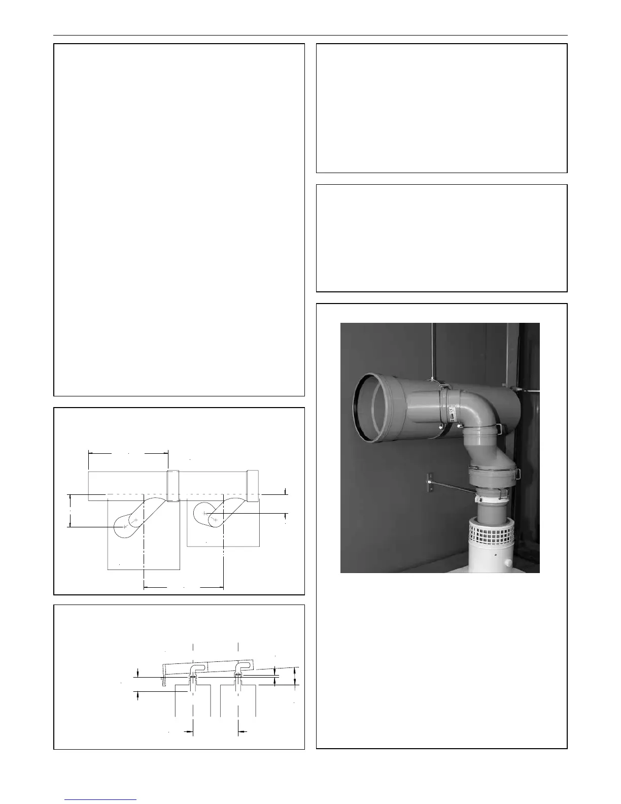
2.8 HEADER INSTALLATION
The Cascade Header is suspended from a ceiling or overhead
structure by studding attaching to brackets holding the
circumference of the header duct. There is one bracket and
stud rod supplied with each of the Starter & Extension Kits.
(Fig 2.9)
The boiler ue tube of each boiler is secured by a clamp and
tie rod either to a wall or supporting structure. (Fig 2.9)
FIGURE 2.9
Support
Bracket
Clip
Clip
Clip
Clip
FIGURE 2.6 CONDENSATE
FALL DIMENSIONS
Wire retaining clips are also tted to the starter kit
End Cover and Syphon connection (not shown).
Refer to diagrams shown in pages 10-13 for
correct location of all wire retaining clips.
Important: All wire retaining clips must be tted
to the ductwork to ensure safe operation of the
system.