IMPORTANT - when lling:
When lling there may be a slight water leak from the air vent therefore electrical connections should be protected.
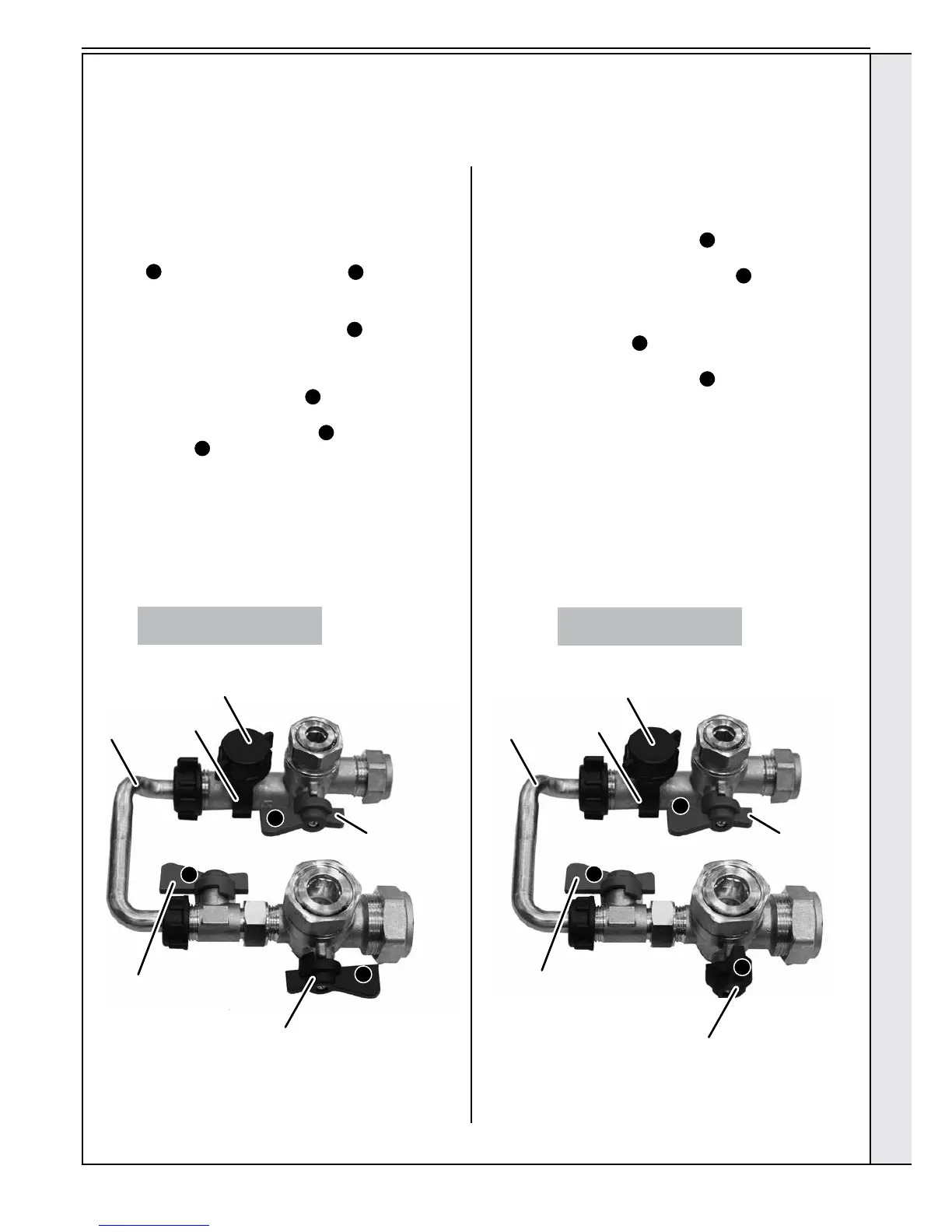
Filling
1. Ensure lling loop is connected and all washers in place.
2. Ensure dust cap on auto air vent is slackened off.
3. Check the following isolation handles on water connections
are in the horizontal lling position (blue handle on DHW
inlet
A
and black handle on CH return
C
).
Note. The CH ow isolation valve handle MUST be in the
vertical position to enable lling.
4. Slowly turn the lling loop handle (blue
B
) to the
horizontal open position until the pressure gauge reads
between 1 to 1.5 bar.
5. Once the pressure gauge dial reads between 1 to1.5 bar
turn the lling loop handle (blue
B
) back to the closed
(vertical) position.
6. Turn the CH Return handle (black
C
) and the DHW Inlet
handle (blue
A
) to the open (vertical) position.
7. Disconnect the lling loop from the DHW Inlet valve and t
the grey cap to the open end.
8. Fit the Plug to the free end of the lling loop.
Note open all DHW taps to ensure water is owing freely-once
satised close all taps.
Top Up
1. Ensure lling loop is connected and all washers in place.
2. Ensure dust cap on auto air vent is slackened off.
3. Turn the DHW Inlet handle (blue
A
) to the horizontal
position.
4. Slowly turn the lling loop handle (blue
B
) to the
horizontal open position until the pressure gauge reads
between 1 to 1.5 bar
5. Once the pressure gauge dial reads between 1-1.5 bar
turn the handle (blue
B
) on the lling loop back to the
closed (vertical) position.
6. Turn the DHW Inlet handle (blue
A
) to the open (vertical)
position.
7. Disconnect the lling loop from the DHW Inlet valve and t
the grey cap to the open end.
8. Fit the Plug to the free end of the lling loop.
Note open all DHW taps to ensure water is owing freely-once
satised close all taps.
FILLING
A
A
B
C
B
C
CONNECTIONS & FILLING...... CONT’D
Filling Loop
(Blue)
Filling Loop
(Blue)
CH Return
(Black)
CH Return
(Black)
DHW Inlet
(Blue)
DHW Inlet
(Blue)
Cap
Cap
Plug
Plug
Filling
Loop
Filling
Loop
Filling Positions shown
Top Up Positions shown
INSTALLATION
 Loading...


