45
REPLACEMENT OF COMPONENTS
GENERAL
1. Isolate the electricity supply.
2. Turn off the gas supply.
3. Remove the boiler front panel. Refer to Frame 39.
4. Release the retaining clip and swing the control box down
into its servicing position.
After replacing ANY component check operation of the
boiler, including gas tightness, gas rate and combustion
test.
IMPORTANT.
When work is complete, the front panel must be correctly
retted - ensuring that a good seal is made.
Notes.
1. In order to assist fault nding, the control panel has
an LED diagnostic display. The key to boiler fault
conditions is shown in Frame 73.
2. In order to replace components in Frames 60-71 it is
necessary to drain the boiler. Refer to Frame 59.
THE BOILER MUST NOT BE OPERATED WITHOUT THE FRONT PANEL FITTED
4
46
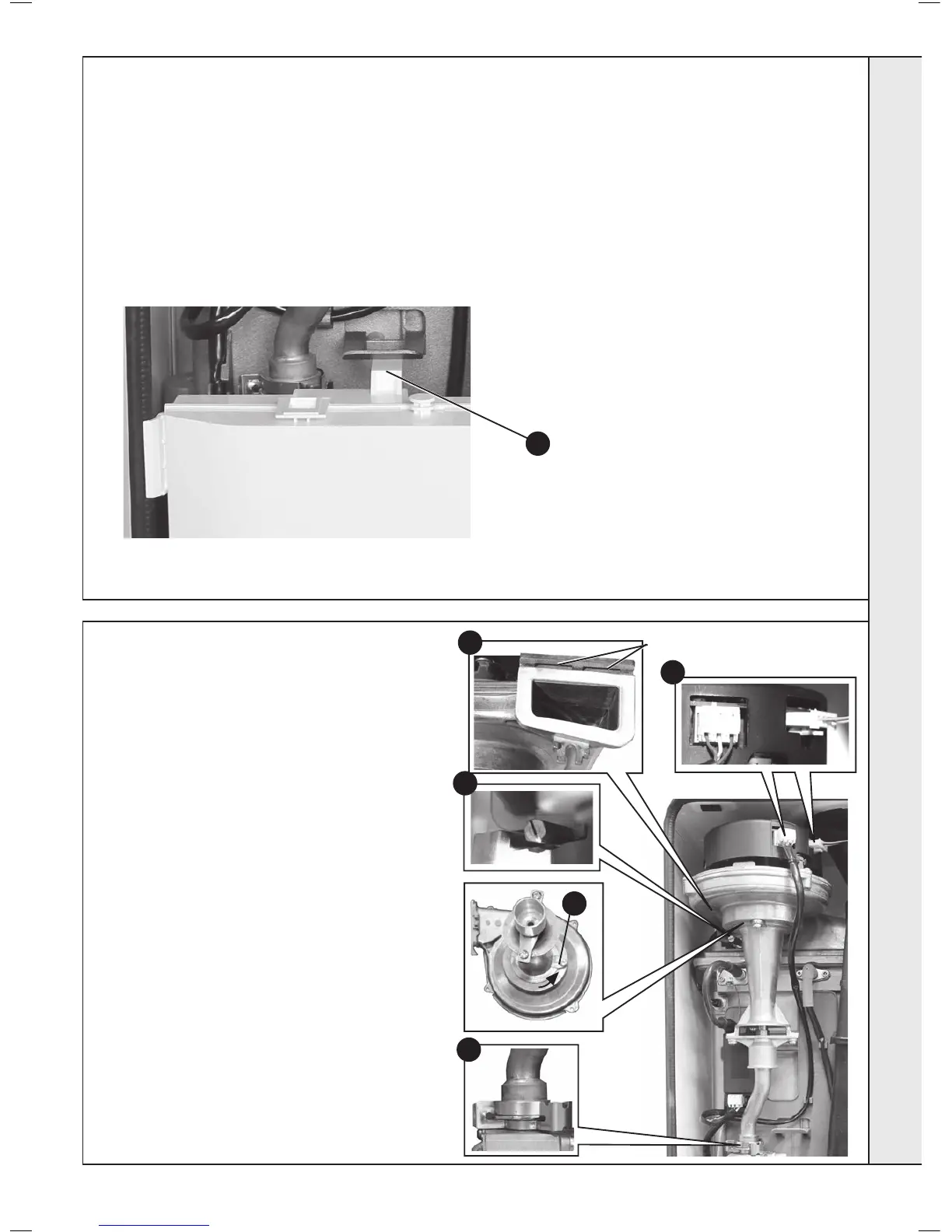
FAN REPLACEMENT
1. Refer to Frame 45.
2. Disconnect the electrical leads from the fan.
3. Remove the clip from the gas control valve
outlet.
4. Remove the extended nut retaining the fan
mounting bracket.
5. Lift and remove the fan and venturi assembly.
6. Remove the screw and twist venturi anti-
clockwise to remove venturi assembly, noting
the orientation of the venturi in relation to the
fan body.
7. Transfer the venturi assembly to the new fan,
replacing the ‘o’ ring if evidence of damage or
deterioration is visible.
8. Fit the new fan / venturi assembly ensuring the
retaining tabs are correctly positioned and the
fan outlet sealing gasket is correctly positioned
and free from damage. Ret the extended nut.
9. Reassemble the boiler in reverse order, taking
care not to overtighten the screw on the fan
mounting bracket and ensure all gas ‘o’ rings
are in place
10. Check the operation of the boiler. Refer to
Frames 32 & 36.
2
4
6
8
Retaining Tabs
3
 Loading...


