EasyManuals Logo

IDEAL LOGIC+ Combi 24 User Manual

IDEAL LOGIC+ Combi 24
20 pages
To Next Page IconTo Next Page
To Previous Page IconTo Previous Page
Page #5 background image
5
Signal
B
A
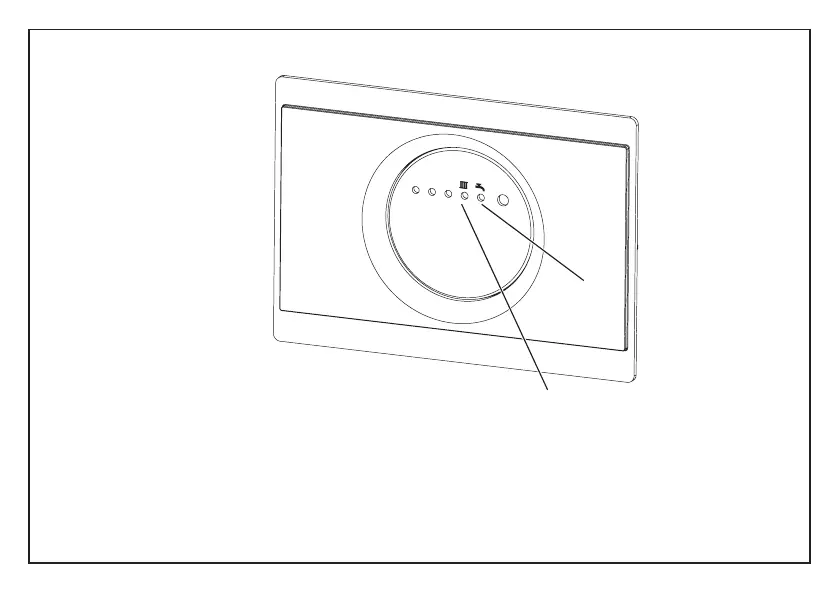
RECEIVER UNIT (BOILER MOUNTED)
1. During normal operation light (A) is on for Hot water Operation.
2. During normal operation light (B) is on for Central Heating Operation.
3. If the Reset Button is pressed on the room thermostat the signal lights on the receiver unit will light. If less than
4 lights are on either the room thermostat is too far from the boiler or the batteries in the room thermostat need
replacing.
At the same time “M-050 S-050” is shown on the room thermostat. The number is another indicator of signal
strength - the lower the number the better.
204796-6.indd 5 15/12/2011 14:34:24
back

Other manuals for IDEAL LOGIC+ Combi 24

Questions and Answers:

Question and Answer IconNeed help?

Do you have a question about the IDEAL LOGIC+ Combi 24 and is the answer not in the manual?

IDEAL LOGIC+ Combi 24 Specifications

General IconGeneral
ModelLogic+ Combi 24
CategoryBoiler
Boiler TypeCombi
Fuel TypeNatural Gas
MountingWall-mounted
ERP RatingA
Output24 kW
Efficiency94%
Dimensions (H x W x D)700 x 395 x 278 mm
Max. Working Pressure3 bar
Central Heating Flow Temperature Range30-80°C
Warranty7 years

Related product manuals