GENERAL
Mini --- Installation & Servicing
12
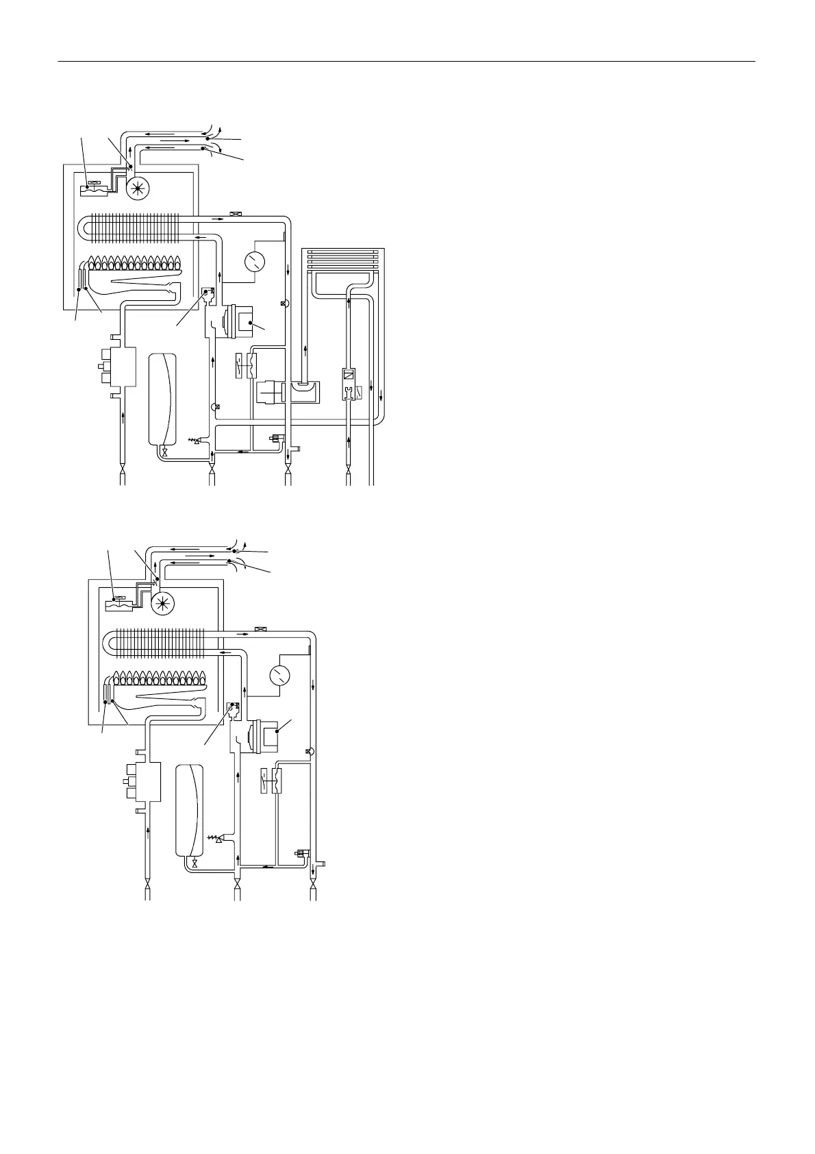
7BOILERWATERCIRCUITDIAGRAM
M i n i C 2 4 --- M i n i C 2 8 --- M i n i C 3 2
32
1
2
34
5
6
7
8
9
10
11
12
13
14
15
16
17
18
19
20
21
23
24
25
22
26
27
28
29
30
31
33
Mini S24 --- Mini S28
33
6
7
8
9
10
11
12
13
14
15
16
17
18
19
20
21
23
24
25
22
26
27
28 29
30
31
1 Domestic hot water (DHW) heat exchanger
2 Domestic hot water (DHW) flow switch
3 Domestic hot water (DHW) outlet pipe
4 Domestic cold water inlet cock
5 Three---way diverter valve
6 Main circuit drainage cock
7 Central heating flow cock
8 B y --- p a s s v a l v e
9 Central heating (CH) return cock
10 3 bar pressure relief valve
11 Gas cock
12 Expansion vessel
13 Gas valve inlet pressure tap
14 Modulating gas valve
15 Burner pressure tap
16 Flame detection electrode
17 Ignition electrodes
18 Burner
19 Combustion chamber
20 Primary heat exchanger
21 Fan
22 Air pressure switch
23 Ventur i device
24 Flue outlet pipe
25 Air intake pipe
26 Automatic air vent
27 Overheat thermostat
28 Pump
29 Pump vent plug
30 CH temperature probe
31 CH flow switch
32 DHW temperature probe
33 CH circuit temperature/pressure gauge
 Loading...