INSTALLAT ION
Mini Installation & Servicing
13
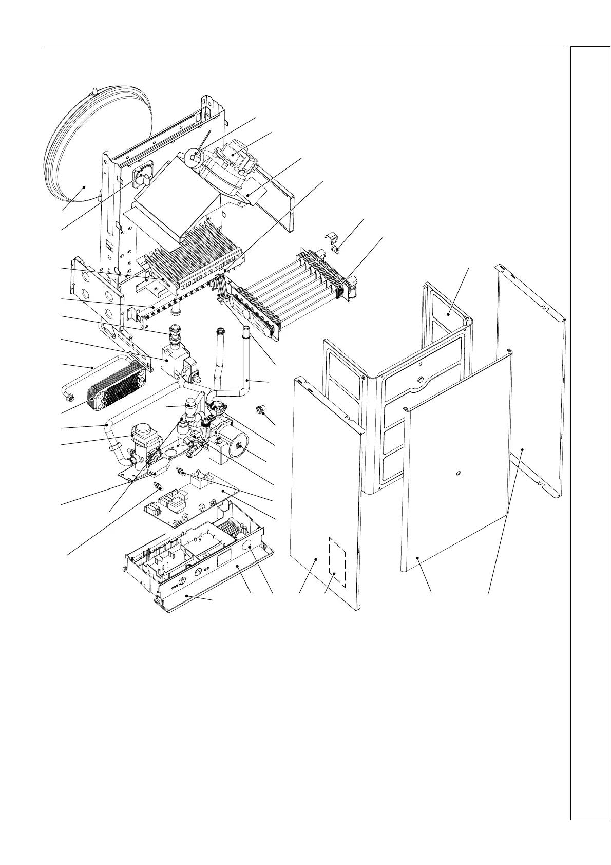
8 B O I L E R A S S E M B LY ---
Exploded View
19
2
35
13
28
7
9
20
4
1
25 23
5
15
18*
14
16
17
26
12
10
27*
29*
30
11*
31
32
34
33
8
6
3
22
36
2124
P5
1Venturi
2Fan
3 Flue hood
4 Flame detection electrode
5 Overheat thermostat
6 Primary heat exchanger
7 Inner case cover
8 Ignition electrodes
9 Heat exchanger return pipe
10 CH temperature probe
11 DHW temperature probe
12 Main circuit drainage cock
13 Auto air vent
14 Pump
15 Electronic control pcb
16 3 bar pressure relief valve
17 Return manifold
18 DHW flow switch*
19 Right hand panel
20 Boiler front panel
21 Appliance data badge (inside)
22 Left hand panel
23 CH circuit pressure gauge
24 Model identification & instructions
25 Control panel door
26 CH flow switch
27 3 way diverter valve*
28 Heat exchanger flow pipe
29 DHW heat exchanger*
30 Bypass pipe
31 Gas valve
32 Gas valve outlet pipe
33 Injector manifold
34 Burner
35 Air pressure switch
36 Expansion vessel
INSTALLATION
* Mini C24, Mini C28 and Mini C32 only
 Loading...