INSTALLAT ION
Mini --- Installation & Servicing
16
11 FITTING THE FLUE SYSTEM (cont.)
Co---axial Flue kits.
Horizontal.
For calculation of total flue length, the distance MUST be
measured from the centreline of the concentric elbow to the
end of the terminal grille.
Vertical outlet
For calculation of total flue length, the distance MUST be
measured from the centreline of the outlet connector at the
boiler top panel to the end of the terminal grille.
For each additional 45˚ and 90˚ flue bend used, the
maximum permissible length of flue system must be reduced
by 1m or 1,5m respectively.
Horizontal and Vertical Outlet kits (60 --- 100) have a minimum
300mm length, up to a maximum shown in tables 7 & 8.
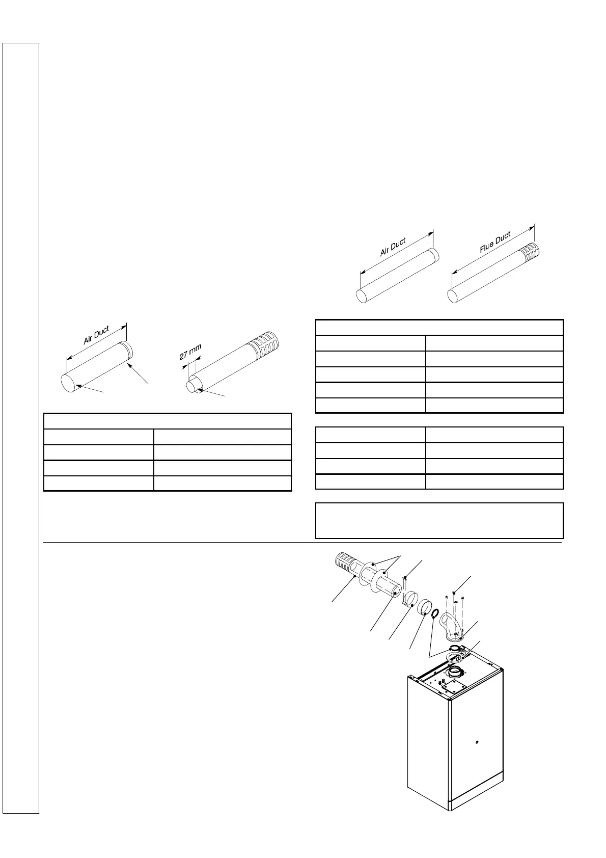
Cutting lengths of flue and air ducts
Measure the wall thickness and, when using a side outlet, the
gapbetweentheinnerwallandtheboilersidecasing.
Use the following chart to calculate the cutting length of air
duct.
Completely insert the flue duct in the air duct.
Mark and cut the flue duct so it protrudes 27 mm from the air
duct edge.
Groove
Cut this end
Flue duct
12
Horizontal Concentric
Air duct
Rear Outlet Wall thickness + 67 mm
Rear outlet + Stand ---off W all thickness + 102 mm
S i d e O u t l e t --- L H & R H Wall thickness + Gap + 120mm
Twin pipe flue kits
For calculation of total flue length, the distance MUST be
measured from the centreline of the flue duct/air duct
connection to the end of the flue outlet grille/air inlet duct.
For each additional 45˚ M&F and 90˚ M&F flue bend used,
themaximumpermissiblelengthoffluesystemmustbe
reduced by 0,9m or 1,65m respectively.
For each additional 90˚ F&FFluebendused,themaximum
permissiblelengthoffluesystemmustbereducedby2,75m.
Lengths of allowable equivalent flue outlet and air inlet ducts
are indicated in the graphs within this frame.
N.B.: The air intake and flue outl et must not terminate on
opposite sides of the building.
Cutting lengths of flue and air ducts
Measure the wall thickness and, when using a side outlet, the
gap between the inner wall and the boiler side casing. Use
the following chart to calculate the cutting lengths of both flue
and air ducts.
Twin Pip e
Air duct
Rear Outlet W all thickness + 215 mm
Rear outlet + Stand--- off Wall thickness + 250 mm
Side Outlet --- LH Wall thickness + Gap + 83 mm
Side Outlet --- RH Wall thickness + Gap + 273mm
Flue Duct + Grille
Rear Outlet W all thickness + 225 mm
Rear outlet + Stand--- off Wall thickness + 260 mm
Side Outlet --- LH & RH W all thickness + Gap + 278mm
When installing a horizontal flue system, Co---axial or
Twin Pipe, all ducts MUST have a fall of 3% AWAY from
the boiler.
12 REAR FLUE ASSEMBLY
Legend
1 Wall finishing gaskets
2 Self tapping screw 4,2x13
3 Self tapping screws 4,8x13
4 Flue turret
5 Boiler ---turret gasket
6 Fluepipegaskets
7 Turret---air pipe gasket
8Band
9 Flue pipe ø 60 mm with terminal grille assembly
10 Air intake pipe ø 100 mm
9
10
8
7
6
5
4
3
1
2
INSTALLATION
 Loading...