INSTALLAT ION
Mini Installation & Servicing
15
11 FITTING THE FLUE SYSTEM
The maximum total equivalent lengths are given in
Table 7 and Table 8 for co---axial pipes ø 60---100 mm,
Ta b l e 9 f o r c o --- a x i a l p i p e s ø 8 0 --- 1 2 5 m m a n d i n t h e
diagrams for the ø 80 mm twin pipes air---flue systems.
Refer to the assembly instructions contained within the
chosen flue kit packaging for the correct assembly and
installation.
Condensate Collection
When a length of vertical pipe is used in the system and the
length of flue exceeds the following, a condensate drain and
trap must be fitted to the lowest point of the system.
The trap must be connected to a suitable waste pipe.
ø80---125mm co---axial pipes --- 1 metres
ø80twinfluepipes ---7metres
Flue Restrictors
Two different sized restrictors are supplied with the
boilers Mini C24, Mini S24, Mini C28, Mini S28.
A 44 mm size is fitted to the boiler and a 47 mm size is
supplied in a separate bag.
Two different sized restrictors are supplied with the boiler
Mini C32
A 47 mm size is fitted to the boiler and a 50 mm size is
supplied in a separate bag.
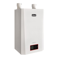
The appropriate restrictor, when necessary, must be fitted in
the flue outlet elbow as indicated in following picture.
For the correct use of the restrictors with co---axial pipes
ø 60/100 mm refer to:
Tab le 7 f o r m od els Mini C24, Mini S24, Mini C28, Mini S28.
Tab le 8 f o r m od el Mini C32
For the correct use of the restrictors with vertical roof kit ø
80/125 mm refer to:
Tab le 9 f o r m od els Mini C24, Mini S24, Mini C28, Mini S28
Table 10 for model Mini C32.
Table 7 --- Models Mini C24, Mini S24, Mini C28, Mini S28
Pipe length (ø 60/100) Restrictor
Between 0,5 (19.5“) and 1 m (39“) ø44mm
More than 1 m (39“) up to 2 m (78.5“) ø47mm
More than 2 m (78.5“) up to 4 m (157“) no restrictor
Ta b l e 8 --- M o d e l M i n i C 3 2
Pipe length (ø 60/100) Restrictor
Between 0,5 (19.5“) and 1 m (39“) ø47mm
More than 1 m (39“) up to 2,7 m (8’ 10“) no restrictor
Table 9 --- Models Mini C24, Mini S24, Mini C28, Mini S28
Pipe length (ø 80/125) Restrictor
Between 0,5 (19.5“) and 1,5 m (59“) ø44mm
More than 1,5 m (59“) up to 6,5 m (21’ 4“) ø47mm
More than 6,5 m (21’ 4“) up to 8,5 m
(27’ 10“)
no restrictor
Ta b l e 1 0 --- M o d e l M i n i C 3 2
Pipe length (ø 80/125) Restrictor
Between 0,5 (19.5“) and 4 m (13’ 1“) ø47mm
More than 4 m (13’ 1“) up to 6 m (19’ 8“) no restrictor
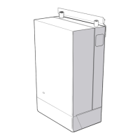
For the correct use of the restrictors with twin pipes refer to
the following diagram for the models Mini C24, Mini S24,
Mini C28 and Mini S28.
0
2
4
6
8
10
12
14
16
18
20
22
24
26
28
30
32
0 2 4 6 8 10 12 14 16 18 20 22 24 26 28 30 32
Flue exhaust (m)
Air intake (m)
Mini C24
Mini S24
Mini C28
Mini S28
Allowed values
Restrictor
47 mm
No
Restrictor
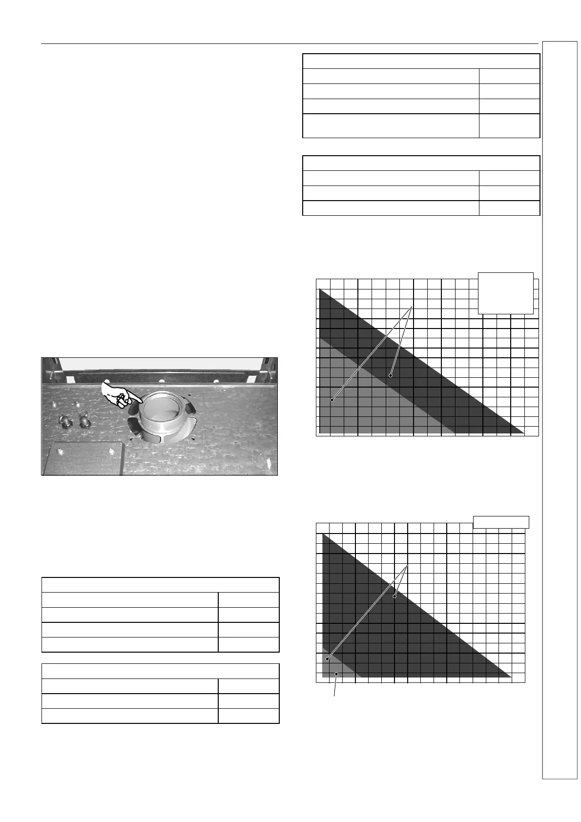
Refer to the following diagram for the model Mini C32.
0
1
2
3
4
5
6
7
8
9
10
11
12
13
14
15
16
0 1 2 3 4 5 6 7 8 9 10 11 12 13 14 15 16
Flue exhaust (m)
Air intake (m)
Mini C32
Restrictor
50 mm
No
Restrictor
Allowed values
INSTALLATION
 Loading...