INSTALLAT ION
Mini --- Installation & Servicing
20
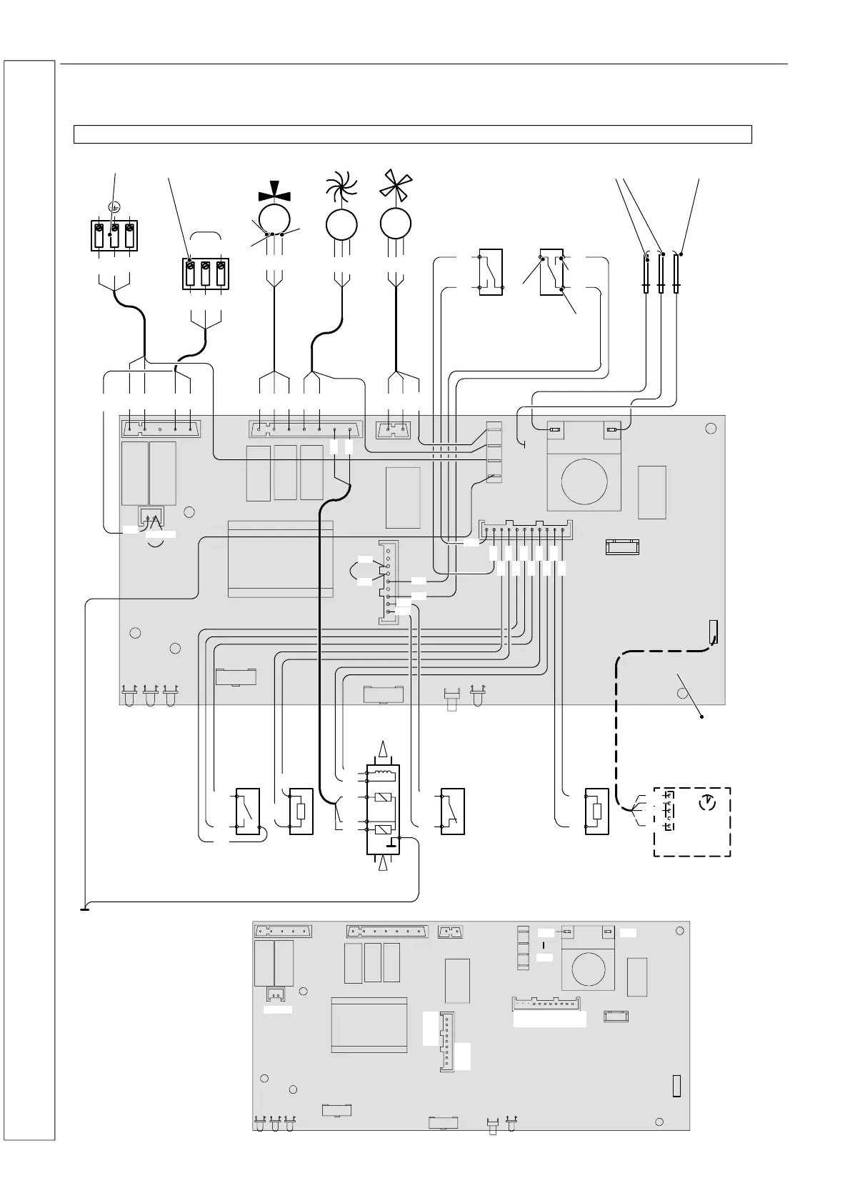
22 PICTORIAL WIRING
Mini C24, Mini C28, Mini C32
LD1LD2LD3
F1
F2
K1
K3 K4
LD4
P4
X6
X1
X7
P5
SB1
X5
K2
X3
X2
X4
123
LN
M
~
3
2
1
X11
M
~
t
t
Ignition
electrodes
Flame detection
electrode
External controls
terminal block
Electric supply
terminal block
Three way
diverter valve
Pump Fan
M
~
Primary circuit
flow switch
Air pressure
switch
D.h.w. flow
switch
C.h. temperature
probe NTC
Modulating
gas valve
Safety
thermostat
D.h.w. temperature
probe NTC
bn = brown
bu = blue
bk = black
wh = white
rd = red
gy = grey
gn = green
ye = yellow
vt = violet
og = orange
gnye = green/yellow
bu
bn
gnye
bu
bn
bk
bn
bu
bn
bu
bk
bu
bn
gnye
bn
bu
bk
bu
bn
bk
bu
bn
bu
bk
gnyebu
bk
gnye
bk
bk
gy
gy
gy
gy
bn
bu
bk
rd
rd
bk
bk
bk
bk
ye
gy
bu
bu
rd
bu
wh
X8
ye
rd
rd
gy
wh
bu
rd
bu
bu
bk
bn
bubu
Wiring diagram for boiler equiped with electronic control p.c.b. type: Bertelli & Partners DIMS11---SA03/16740
NC
COM
NO
rd
wh
gn
bk
Time switch
Electronic control P.C.B.
LD1LD2LD3
F1
F2
K1
K3
K4
LD4
P4
X6
X1
X7
P5
SB1
X5
K2
X3
X2
X4
X8
1 2 3 4 7 8 95 10 11 12 13 14
15 16
17 18
19
20
21
22
23
24
25
26
27
28
29
30
31
32
33
34
35
36
37
38
Electronic
control p.c. b .
Pin position ref. numbering
39
6
rd
rd
bu
bn
bu
INSTALLATION
 Loading...