INSTALLAT ION
Mini Installation & Servicing
19
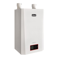
19 SAFETY VALVE DRAIN
The discharge pipe should be positioned so that the
discharge of water or steam cannot create a hazard to the
occupants of the premises or damage to electrical
components and wiring.
Pressure
Discharge pipe
relief valve
20 ELECTRICAL CONNECTIONS
Warning. This appliance MUST be efficiently earthed
A mains supply of 230 V ~ 50 Hz is required.
Mains wiring should be 3 core PVC insulated flexible cord
NOT LESS than 0.75 mm
2
(24 x 0.2mm) and to BS. 6500,
Table 16. (0.5mm
2
flex is not acce ptable --- for mechanical,
not electrical reasons.)
Mains wiring external to the boiler MUST be in accordance
with the current I.E.E. (BS7671) Wiring Regulations and any
local regulations.
For Ireland reference should be made to the current ETCI
rules for electrical installations.
The supply connection is intended to be made via a double
pole switch having a 3 mm (1/8”) contact separation in both
poles, serving only the boiler and system controls. A 3 pin
UNSWITCHED socket may, alternatively, be used.
The fuse rating should be 3.15 AF.
Mini C24, Mini C28 Mini C32 only
F or external controls wiring see frame 26.
Note: the switch contacts of any external programmer,
room or frost thermostat must be volt free.
Connecting a switched live feed to external controls
terminal block may be dangerous and will result in
serious damage to the boiler.
For Mini S24, Mini S28 refer to frame 27.
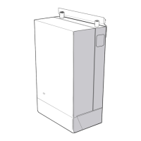
21 ELECTRICAL CONNECTIONS
Incoming mains wiring detail
To gain access to the power supply and external controls
terminal blocks:
1 Remove the screws A and the front panel of the case.
A
2 Remove the screws B.
3 Loosen the screws C.
C
B
B
C
4 Remove the side panels or move the lower part of the side
panels and pull the control panel.
When completely pulled out, the panel can rotate 45˚
downwards to facilitate the operations on the internal parts.
5 Loosen the screws D and remove the service panel.
D
12
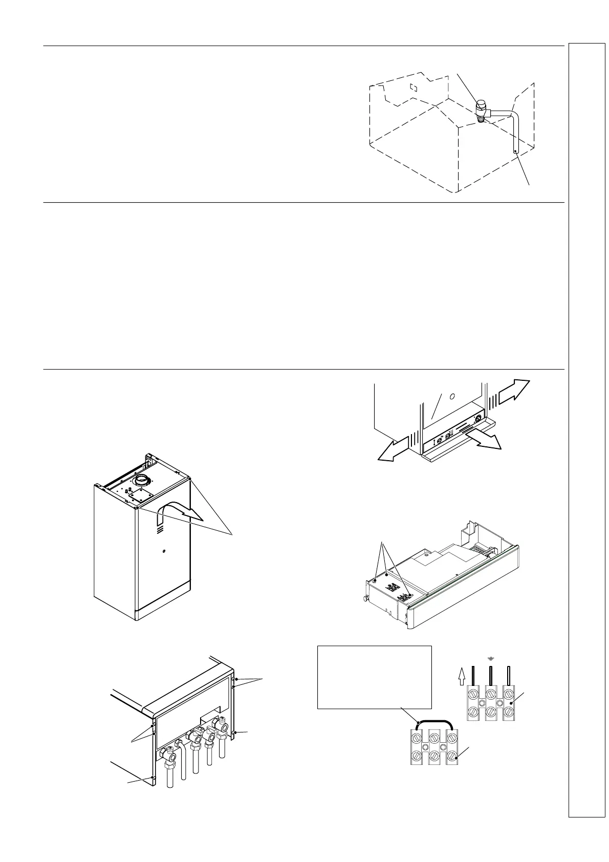
LN
3
Mains
Power supply
terminal block
External controls
terminal block
Mini C24, Mini C28 ,
Mini C32 only
Thermostat link.
Remove when wiring
external thermostats.
Refer to frames 26 and 27
Note: Ensure that the lengths of the current conductors are
shorter than the earth conductor so that i f th e cable slips in its
anchorage the current carrying conductors become taut
before th e earth conductor.
INSTALLATION
 Loading...