INSTALLATION
Solar Thermal - Installation and Servicing
15
OPERATING TIPS - SOLAR POWER SYSTEM (TS 8000)
INSTALLATION
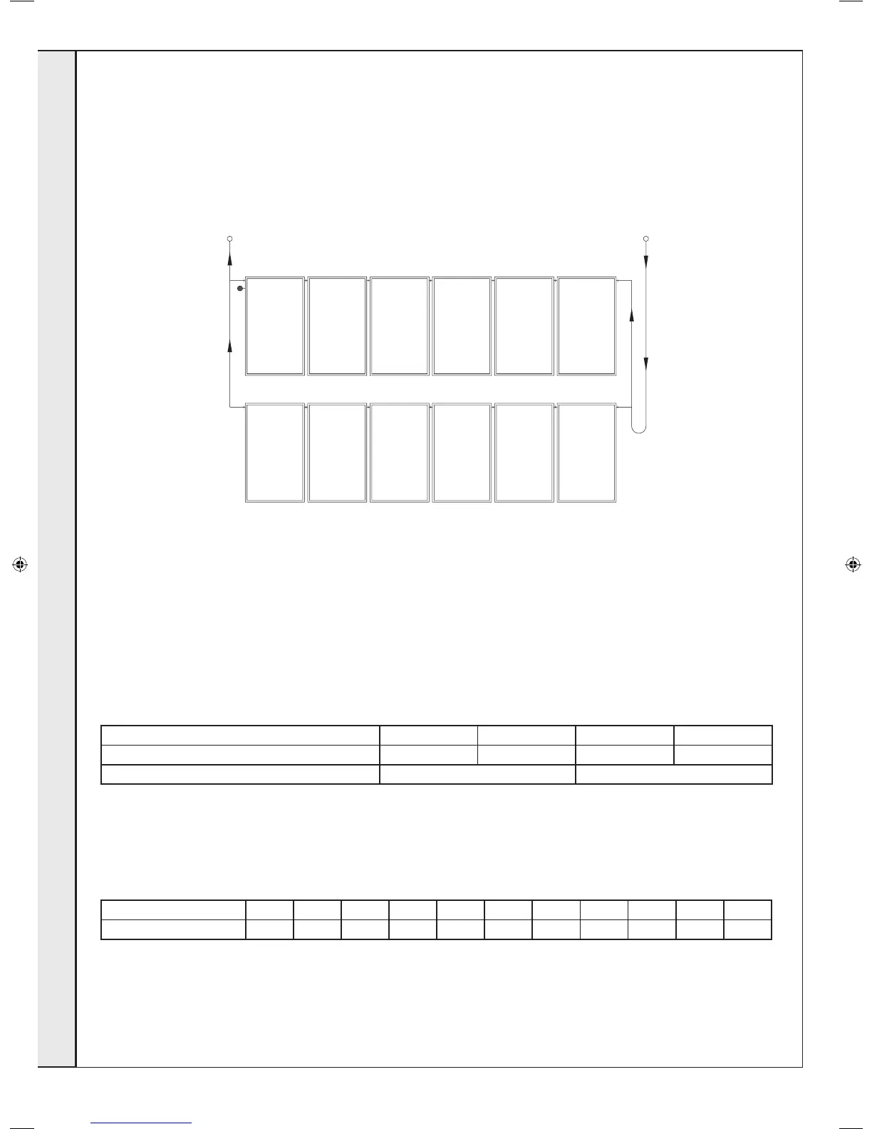
Connecting the collectors to one another
The diagram below is an example of how the collectors can be connected to one another. However, the actual connection may
be different depending on structural conditions. A maximum of 6 collectors may be connected in a series. If a collector panel is
made up of more than 6 collectors, the panel must be connected several times in parallel.
Mass Flow Rate
To ensure the performance of the collector, a specic ow rate of 30 l/m
2
h is to be selected up to a collector panel size of approx.
25m
2
.
Pipe Diameters
Dimensions table with a specic ow rate of 30 l/m
2
h
Collector panel size [m
2
] approx. 5 approx. 7.5 approx. 12.5 approx. 25
Pipe diameter / copper [mm] 10 - 12 15 18 22
Pipe diameter / stainless steel corrugated pipe DN16 DN20
Pressure loss collctor for anti-freeze / water mixture (40% / 60%) at a thermal conducting temperature of 50ºC
Pressure loss curve: ∆p = 0,000128x
2
+ 0,022931x
Mass ow rate [kg/h] 0 50 100 150 200 250 300 350 400 450 500
Pressure loss [mbar] 0 1,5 3,6 6,3 9,7 13,7 18,4 23,7 29,7 36,2 43,5
Supply
Return
207786-2.indd 20 16/02/2012 11:26:03
 Loading...