INSTALLATION
Solar Thermal - Installation and Servicing
PUMP STATION
39
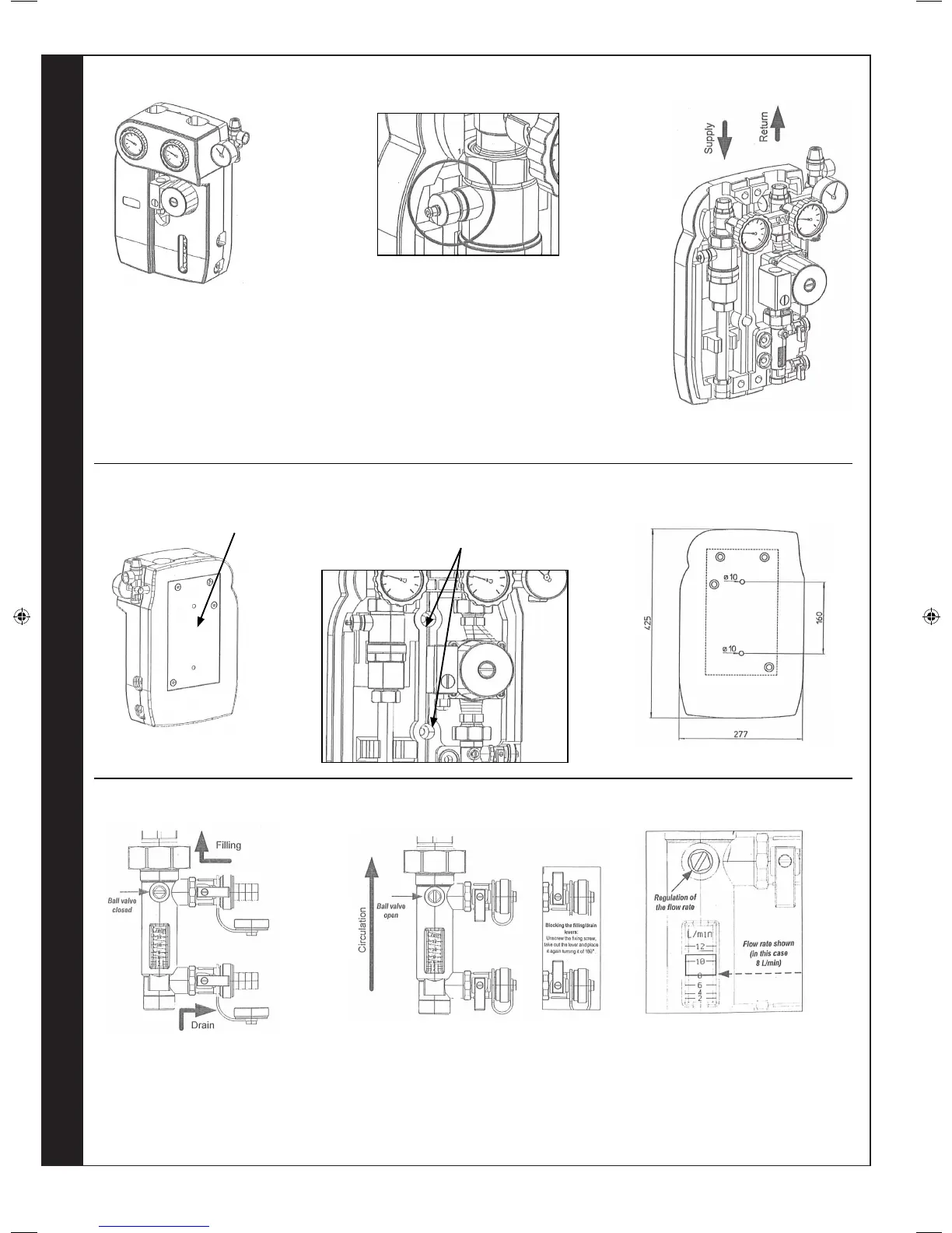
PUMPING STATION 2-WAY “SOLAR 3”
EPP insulation box
Mesurements 277x425x150
side opening on the back part of
the insulation box for the security
unit. A special window allows to
read to adjust the ow without
taking off the cover. Back plate to
fasten the unit to the wall or to the
cylinder.
Back plate to fasten the unit to
the wall or to the cylinder
Fastening holes on the back xing
plate. special openings on the
insulation box allow the fastening
without disassembling the unit.
(1) - Filling the installation:
Remove the plugs from the side
valves and connect the hose unions.
Close the ball valve and open the side
lling valve and draining valve.
Directions for the use of the owmeter to ll the installation:
(2) - Starting the installtion working:
Open the ball valve and close the side
lling and draining valves. Remove the
hose unions and screw again the plugs.
to avoid any casual opening of the side
valves, it is better to stop the levers in
the close position, as shown here aside.
(3) - Regulate the ow rate using the
regulation rod until the right ow rate
is shown.
N.B. The ow rate is shwon taking
as reference the lower edge of the
sliding cursor. (see picture).
The vent air is a device that divides continually the air
that can be in circulation together with the uid. The
air goes to the upper part of the vent air and it can be
eliminated through the special drain while the installation
is working. unscrew of 360º the knurled metal ring lock.
This operation ahs to be done at intervals.
DANGER OF BURNS - To avoid any leakage of the
uid, taking into consideration the very high working
temperature, we recommend to fasten a pipe to the
end of the drain
207786-2.indd 44 16/02/2012 11:26:22
 Loading...