45
INSTALLATION
Solar Thermal - Installation and Servicing
PUMP STATION
Safety Relief Valve / Pressure Gauge Assembly
The Hydraulic solar pump station in the Ideal solar package is equipped with a 6 bar pressure relief valve which should be connected
via 22mm pipe work terminating in a suitable container. An empty canister of heat transfer uid can be used for this purpose .
Drain Valve
It is good practice to install a suitable drain valve at the lowest point in the system to facilitate draining of the solar system if required.
Connecting the Solar Cylinder
Refer to solar cylinder manufacturer’s instructions for installation, observing the correct direction of ow through the cylinder coil. Refer
to Frame 1.
Double Return Kit
If additional ow capacity is requried the single line
pump station (Ideal Part No. UIN 207072) can be
employed. within this kit an additional collector
return pump and connector tee is provided. During
installation the safety relief valve and pressure
gauge is transferred from the twin line pump station
to the single line station.
A ow gauge is provided in the single line pump
station so the ow rate between the two ow rates
can be balanced.
The single line pump station is also employed when
installing solar panels in East-West conguration.
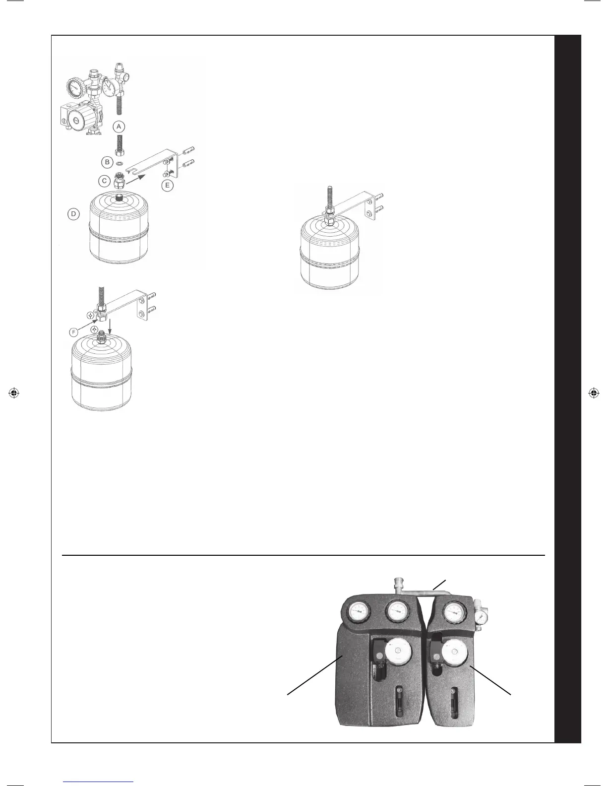
Twin line
pump station
Single line
pump station
Tee Connection
40
BRACKET AND CONNECTION KIT FOR THE EXPANSION VESSEL
A. 3/4” exible pipe connected to the security unit of the solar pumping
station (not included).
B. Fibre sealing joint inlcuded.
C. Connector with double check valve to disconnect the expansion vessel
in a reliable and fast way without any leakage.
D. Expansion vessel with 3/4” threaded connection (available on request).
E. Fixing bracket provided with plugs and screws to x it to the wall
Fix the bracket (E) to the wall with the plugs (centre distance 55mm)
Screw the expansion vessel (D) to the connector (C) and put it on the
xing bracket using the special groove then lock with the nut.
Put the sealing joint (B) and screw the exible pipe of the security unit (A)
to the connector.
Replacement of the Expansion Vessel
The connector (C) holds up the expansion vessel and allows a quick detachment of it avoiding
any leakage.
By unscrewing the nut (F) it is possible to disconnect one end of the connector that remains
screwed to the expansion vessel. The other end of the connector stays xed on the bracket
connected to the security unit.
both ends have a check valve that becomes operative at the time of the disconnection: this
prevents any leakage both from the expansion vessel and from the exible pipe.
To ret the expansion vessel connect the two ends of the connector and to x them by screwing
the nut (F). In that way the two check valves are disconnected and the expansion vessel is
again connected to the installation.
207786-2.indd 45 16/02/2012 11:26:23
 Loading...