55
INSTALLATION
Solar Thermal - Installation and Servicing
INSTALLATION
52
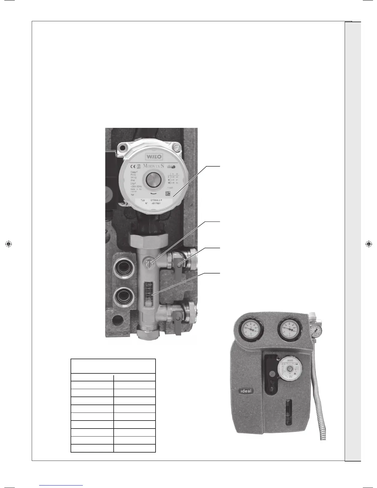
COMMISSIONING THE SYSTEM
1. Set the Solar controller to the “ON” position on the slider
switch (refer to Frame 45), the solar pump station will now
circulate the heat transfer uid around the system. Circulate
until all the air is removed from the system.
2. Once all the air has been removed from the system, turn the
solar controller to the “OFF” position (refer to Frame 45) and
using the ll and drain valve, slowly drain the heat transfer
uid until the system pressure reduces to 1 bar.
NOTE. DO NOT USE THE SAFETY ASSEMBLY PRESSURE
RELIEF VALVE FOR THIS PURPOSE.
m
2
of Collectors l/min
1 1.0
2 2.0
3 3.0
4 4.0
5 5.0
6 6.0
7 7.0
8 8.0
9 9.0
Corresponding Flow Rates for
Ideal Solar Collectors (cold)
3. Turn the solar controller to the “ON” position on the
slider switch (refer to Frame 45)
4. Set the ow rate (see table below) using the speed
setting on the circulation pump and adjustment
screw above the ow measurement display for ne
adjustment.
5. Return the solar controller switch to “Auto” (refer to
Frame 45).
6. Fit the front thermal insulation shell cover engaging the
upper shell rst.
7. The system is now commissioned and available for
normal operation.
Circulation Pump
Adjustment Screw
Fill and Drain Valve
Flow Measure Display
207786-2.indd 55 16/02/2012 11:26:31
 Loading...