7
INSTALLATION
Solar Thermal - Installation and Servicing
2
5
7
9
12
15
L/MIN
bar
6
0
2
4
?C
0
20
40
60
80
100
120
2
5
7
9
12
15
L/MIN
?C
0
20
40
60
80
100
120120
100
80
60
40
20
0
?C
Drain
SunSun
Solar
Cylinder
Expansion
Vessel
*Solar
Cont-
ainer
Safety Relief
Valve / Pressure
Gauge Assembly
Solar
Collector
Panel
Solar
Collector
Panel
T2
Solar
Collector Sensor
T1
Solar
Collector Sensor
sol8618-1
Hot Water to Supply
Back Up
from Boiler or
Immersion Heater
Solar
Cylinder
Sensor
Single
Line
Pump
Station
Twin Line
Pump
Station
Solar
Controller EC2
T3
*Important: solar fluid container should be manufactured from a material
capable of withstanding the high temperatures at which solar fluid operates.
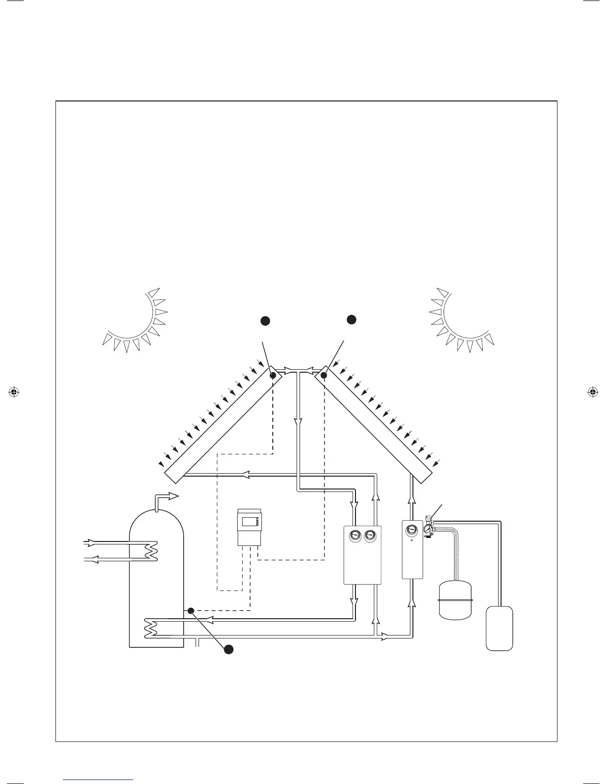
1B
EAST WEST SOLAR PANEL CIRCUIT
Solar panels can be located in an East - West orientation. In this conguration single line pump station (Ideal part No. UIN 207072)
in addition to the twin line pump station should be employed. Control between the panels located in different orientations can be
achieved by specifying the solar controller EC2, (Ideal Part No. UIN 207754), which has the capability to control panels located in
East - West conguration. Controller, installation and operating instructions are provided with the Solar controller EC2 kit.
207786-2.indd 7 16/02/2012 11:25:51
 Loading...