9
INSTALLATION
Solar Thermal - Installation and Servicing
3
COLLECTOR SIZING AND LOCATION
Typically, approximately 1 square meter of solar collector should be supplied for each house occupant. Each Ideal Solar
Collector panel has an external area of 2.02m
2
(TS8000) and 2.51 m
2
(TS8001). Therefore, the Ideal 2 collector array is ideal
for a 3 to 4 person household and the Ideal 3 collector array for a 5 to 6 person household. The collector array should be
located between 30
o
East and 40
o
West of South and at an inclination between 20
o
to 45
o
within these bands there is no more
than a 10% loss in efciency from the optimum south facing at an inclination of 35
o
. For an East-West roof, either an East-
West application can be installed with a collector on each pitch or additional collector(s) can be tted on either the East-West
roof. For example, a 3 collector array on an East facing roof would be ideal for 4 to 5 occupants where there is a 20 % loss in
performance as compared to the ideal South facing 30° pitch. There should be no signicant over-shading of buildings, trees or
other obstructions. Even obstructions to the north of the collector can block a signicant proportion of the diffuse solar radiation.
Signicant overshading can be compensated by over-sizing the solar system.
4
INSTALLATION OF THE COLLECTOR AND EXTERNAL COMPONENTS
The ow and return pipework can be passed
through the roof either with a proprietary
roof penetration tile or a Code 4 lead custom
made roof penetration tile. Ventilation tiles
can sometimes be adapted for this purpose.
Alternatively a silicon “dektite” can be used.
Optional lead pipe ashing tile kits which can be
adapted to suit most roof tiles are available. Any
exposed elements of the roof penetration must be
carefully sealed with exterior grade low modulus
silicone.
IMPORTANT
All connections and joints must be resistant to temperature of up to 200°C and resistant to glycol.
During installation and servicing means for covering the solar collectors will be required to avoid burns. In direct sunlight, the solar
collectors can reach temperatures of 200°C.
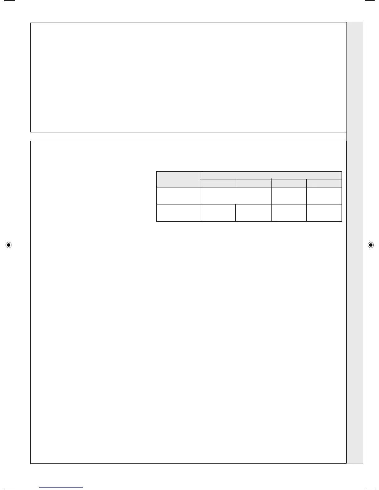
Note. It is recommended that you select the pipework in accordance with this table. If the system provides additional pressure loss
(bends, valves, etc.), you should consider selecting pipe with larger diameter.
The nal part of the roof installation is the insertion of the silicon PT1000 Collector Sensor into its mounting pocket in the Flow
Connector and feeding of the cable through or under the ow roof penetration and through the felt or timber sarking so that the
sensor cable is visible in the loft space.
Wiring run lengths and cross sectional areas for low voltage collector sensor wire:
Lengths up to 50m: 0.75mm
2
Lengths up to 100m: 1.5mm
2
Number of Single Pipe Length
Solar Collectors Up to 6m Up to 15m up to 20m up to 25m
to 5 Ø 15mm (DN12) Ø 22 mm Ø 22 mm
(DN 15) (DN 20)
to 9 Ø 22 mm Ø 22 mm Ø 28 mm Ø 28 mm
(DN15) (DN20) (DN25) (DN25)
INSTALLATION
207786-2.indd 9 16/02/2012 11:25:53
 Loading...