5: SPECIAL FUNCTIONS
5-16 « FC4A MICROSMART USER’S MANUAL »
Ladder Diagram
When the MicroSmart starts operation, reset value 62836 is stored to reset value special internal relay D8046. Gate input
special internal relay M8031 is turned on at the end of the third scan to start the high-speed counter to count input pulses.
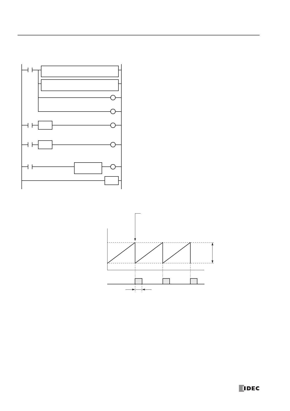
Timing Chart
M8120
M8120 is the initialize pulse special internal relay.
1st scan
SUB and ADD instructions are used to store a reset value of 62836
(65535 – 2700 + 1) to D8046 (reset value).
M8031 (gate input) is turned off.
M0 is turned off.
3rd scan
At the rising edge of M0, M8031 (gate input) is turned on. After the
END processing of the third scan, HSC1 starts counting.
2nd scan
At the falling edge of M8120 (initialize pulse), M0 is turned on.
HSC1 is initialized in the END processing of the second scan.
When HSC1 overflows 65535, output Q1 (comparison output) is
turned on to star t timer T0. HSC1 starts to repeat counting.
When the timer times out 0.5 sec, M8030 (comparison output
reset) is turned on to turn off output Q1.
END
M0
M8031
R
M8031
S
SOTU
REPS2 –
2700
D1 –
D0
S1 –
65535
SUB(W)
REPS2 –
1
D1 –
D8046
S1 –
D0
ADD(W)
M0
R
M8120 M0
S
SOTD
Q1
TIM
5
T0
M8030
Comparison Output Q1
ON
OFF
Current Value D8045
When the high-speed counter current value exceeds
65535, comparison output Q1 is turned on and the
current value is reset to 62836.
Reset Value D8046
62836
65535
0.5 sec for punching
2700 pulses