5: SPECIAL FUNCTIONS
« FC4A MICROSMART USER’S MANUAL » 5-17
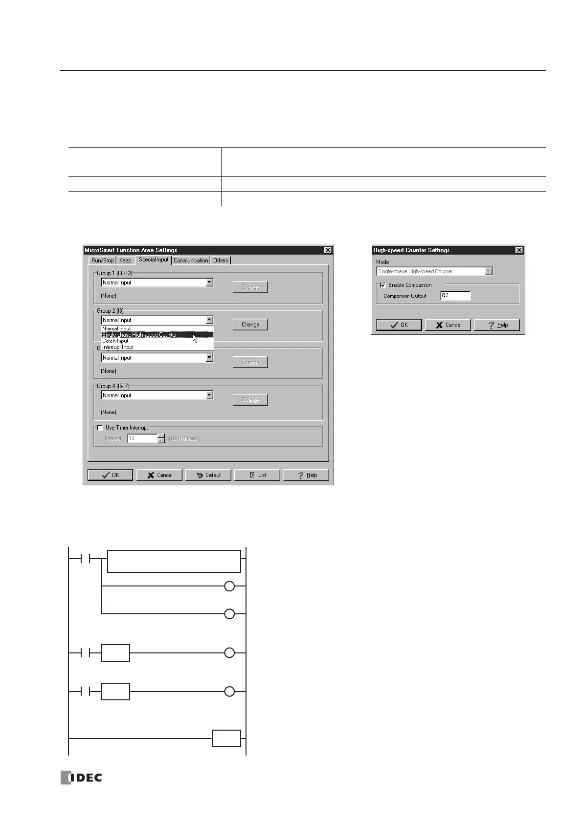
Example: Single-phase High-speed Counter
This example demonstrates a program for single-phase high-speed counter HSC2 to count input pulses and turn on output
Q2 every 1000 pulses.
Program Parameters
Programming WindLDR
Ladder Diagram
When the
MicroSmart starts operation, preset value 1000 is stored to preset value special internal relay D8048. Gate input
special internal relay M8035 is turned on at the end of the third scan to start the high-speed counter to count input pulses.
Group 2 (I3) Single-phase High-speed Counter
Enable Comparison Yes
Comparison Output Q2
HSC Preset Value (D8048) 1000
M8120
M8120 is the initialize pulse special internal relay.
1st scan
MOV instruction stores a reset value of 1000 to D8048 (preset value).
M8035 (gate input) is turned off.
M0 is turned off.
3rd scan
At the rising edge of M0, M8035 (gate input) is turned on. After the END
processing of the third scan, HSC2 starts counting.
2nd scan
At the falling edge of M8120 (initialize pulse), M0 is turned on. HSC2 is
initialized in the END processing of the second scan.
When HSC2 current value reaches 1000, output Q2 (comparison output)
is turned on, and HSC2 star ts to repeat counting from zero.
END
M0
M8035
R
M8035
S
SOTU
M0
R
M8120 M0
S
SOTD
REPS1 –
1000
D1 –
D8048
MOV(W)