2: MODULE SPECIFICATIONS
« FC4A MICROSMART USER’S MANUAL » 2-7
Relay Output Specifications (All-in-One Type CPU Module)
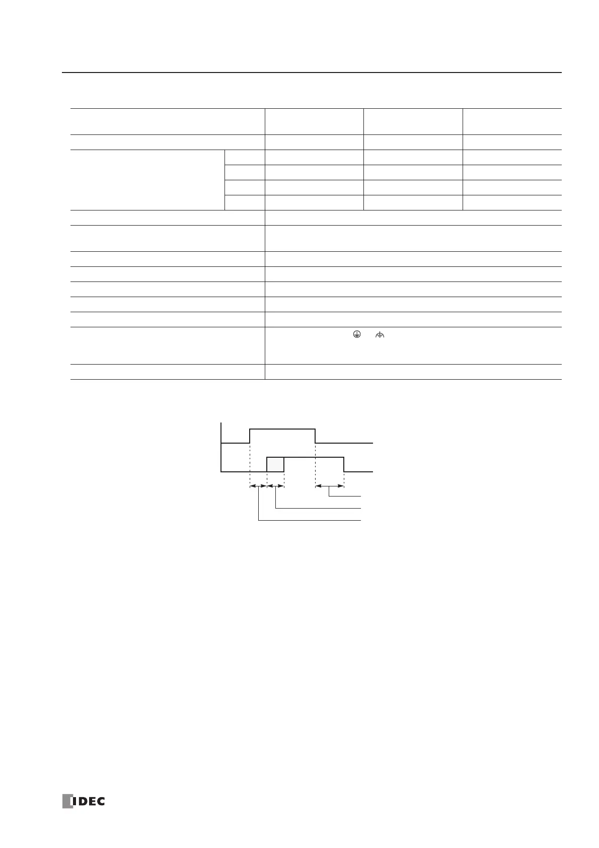
Output Delay
CPU Module
FC4A-C10R2
FC4A-C10R2C
FC4A-C16R2
FC4A-C16R2C
FC4A-C24R2
FC4A-C24R2C
No. of Outputs 4 points 7 points 10 points
Output Points per Common Line
COM0 3 NO contacts 4 NO contacts 4 NO contacts
COM1 1 NO contact 2 NO contacts 4 NO contacts
COM2 —1 NO contact 1 NO contact
COM3 ——1 NO contact
Terminal Arrangement See CPU Module Terminal Arrangement on pages 2-8 and 2-9.
Maximum Load Current
2A per point
8A per common line
Minimum Switching Load 0.1 mA/0.1V DC (reference value)
Initial Contact Resistance 30 mΩ maximum
Electrical Life 100,000 operations minimum (rated load 1,800 operations/hour)
Mechanical Life 20,000,000 operations minimum (no load 18,000 operations/hour)
Rated Load (resistive/inductive) 240V AC/2A, 30V DC/2A
Dielectric Strength
Between output and or terminals: 1,500V AC, 1 minute
Between output terminal and internal circuit: 1,500V AC, 1 minute
Between output terminals (COMs): 1,500V AC, 1 minute
Contact Protection Circuit for Relay Output See page 3-15.