16: INTERFACE INSTRUCTIONS
16-4 « FC4A MICROSMART USER’S MANUAL »
Adjusting Scan Time
The DGRD instruction requires a scan time longer than the filter time plus 6 ms.
The filter time depends on the input terminal used as shown below.
When the actual scan time is too short to execute the DGRD instruction, use the constant scan function. When the input fil-
ter time is set to 3 ms, set a value of 9 or more (in ms) to special data register D8022 (constant scan time preset value). See
page 5-27. When the input filter time is changed, set a proper value to D8022 to make sure of the minimum required scan
time shown above.
Example: DGRD
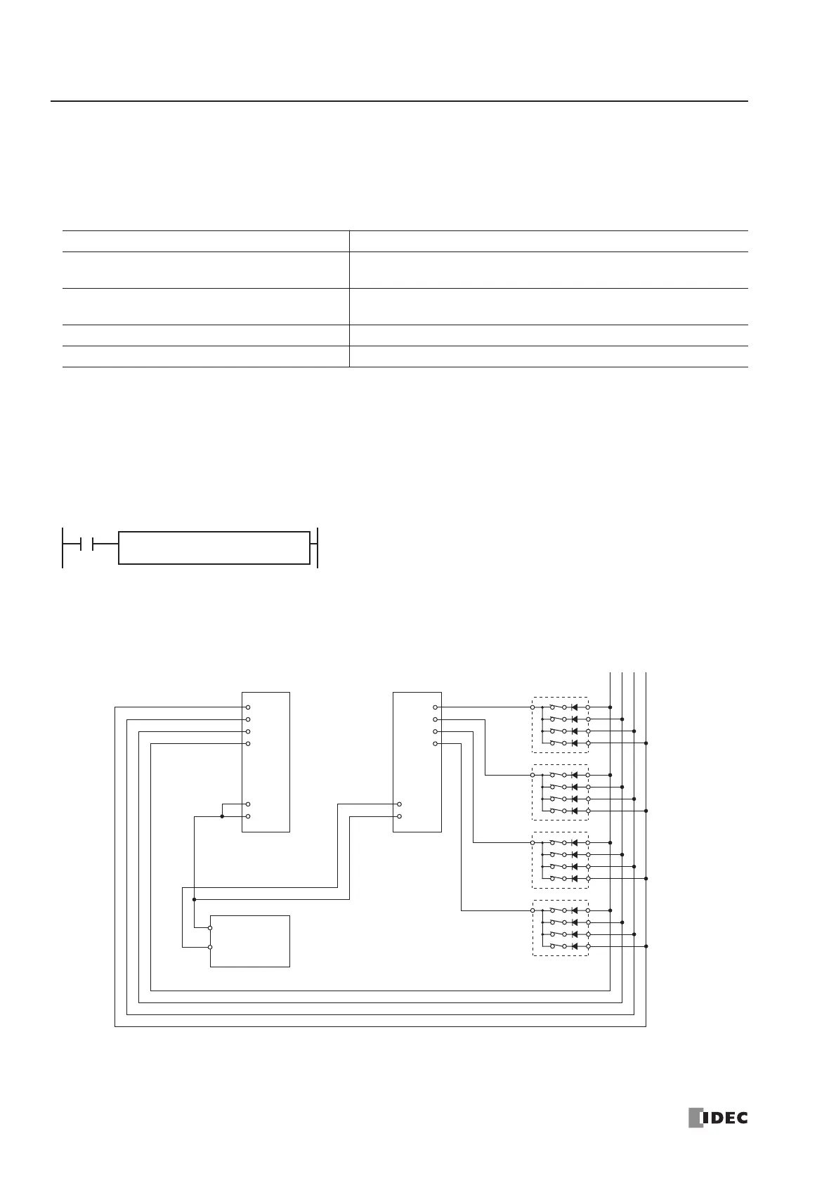
The following example demonstrates a program to read data from four digital switches (IDEC’s DFBN-031D-B) to a data
register in the CPU module, using a 8-point DC input module and a 16-point transistor sink output module.
I/O Wiring Diagram
Minimum Required Scan Time
(Scan time) ≥ (Filter time) + 6 ms
Input Terminals Filter Time
I0 through I7 on CPU Modules
Filter value selected in the Function Area Settings (default 3 ms)
See Input Filter on page 5-24.
I10 through I15 on CPU Modules
(except slim 40-I/O type CPU Module)
3 ms (fixed)
I10 through I27 on slim 40-I/O type CPU Module 4 ms (fixed)
Inputs on Expansion Input Modules 4 ms (fixed)
data register D10.