28: AS-INTERFACE MASTER COMMUNICATION
« FC4A MICROSMART USER’S MANUAL » 28-9
Assigning a Slave Address
AS-Interface compatible slave devices are set to address 0 at factory. Connect the slave to the AS-Interface master module
as shown on page 28-6. Do not connect two or more slaves with slave address 0, otherwise the AS-Interface master module
cannot recognize slave addresses correctly.
1. Power up the MicroSmart CPU module first. Approximately 5 seconds later, turn on the AS-Interface power supply.
Note: When slave address 0 is not mounted on the AS-Interface bus, the CPU module power supply and the AS-Interface
power supply can be turned on at the same time. See page 28-7.
2. From the WindLDR menu bar, select Configure > AS-Interface Master to open the Configure AS-Interface Master
dialog box. Press R
efresh to collect slave information and update the screen display. (When configuration in the
master module is complete, you do not have to press R
efresh since the screen display is updated automatically.)
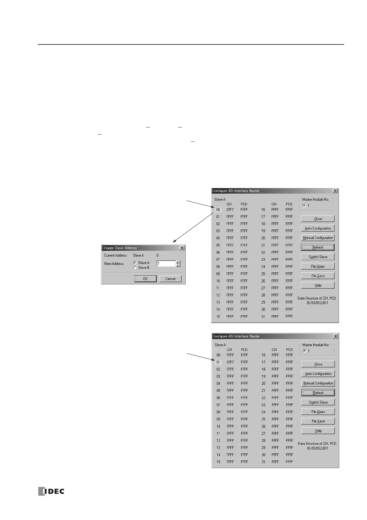
On the Configure AS-Interface Master dialog box, slave address 0 is shaded with yellow. This means that the master mod-
ule has found slave address 0 on the AS-Interface bus. The CDI for address 0 shows 07F7 (ID: 0, I/O: 7, ID2: F, ID1: 7).
3. Click the slave address “00” to open the Change Slave Address dialog box for slave 0. To assign slave address 1
to the slave, enter 1 in the New Address field and click OK.
The new address “01” is shaded with
yellow to indicate that the address
assignment is complete.
4. When changing slave addresses
on other slaves, continue from
step 3 if it is possible to wire the
slave without turning off power, or
from step 1 if the CPU module is
shut down.