APPENDIX
« FC4A MICROSMART USER’S MANUAL » A-5
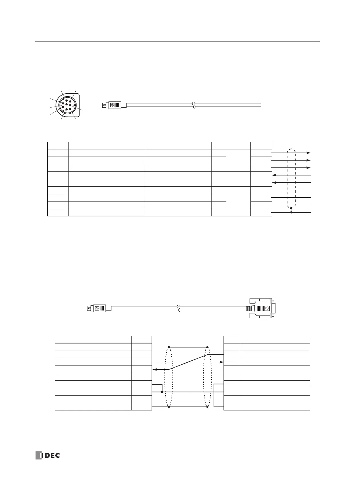
User Communication Cable 1C (FC2A-KP1C)
Cable Length: 2.4m (7.87 feet)
O/I Communication Cable 1C (FC4A-KC1C)
Cable Length: 5m (16.4 feet)
To MicroSmart RS232C Port 1 or 2
To RS232C Port
Attach a proper connector to the open end referring
to the cable connector pinouts shown below.
Mini DIN Connector Pinouts
Note:
When preparing a cable for port 1, keep pins 6 and 7 open. If pins 6 and 7 are connected together, user com-
munication cannot be used.
Pin Port 1 Port 2 AWG# Color
1 NC No Connection RTS Request to Send 28
Twisted
Black
2 NC No Connection DTR Data Terminal Ready 28 Yellow
3 TXD Transmit Data TXD Transmit Data 28 Blue
4 RXD Receive Data RXD Receive Data 28 Green
5 NC No Connection DSR Data Set Ready 28 Brown
6 CMSW Communication Switch SG Signal Ground 28 Gray
7 SG Signal Ground SG Signal Ground 26
Twisted
Red
8 NC No Connection NC No Connection 26 White
Cover ———Shield
Signal Direction
1
2
3
4
5
6
7
8
Mini DIN Connector Pinouts
Description Pin
NC No Connection 1
NC No Connection 2
TXD Transmit Data 3
RXD Receive Data 4
NC No Connection 5
CMSW Communication Switch 6
SG Signal Ground 7
NC No Connection 8
Shield Cover
To MicroSmart RS232C Port 1 or 2
To HG1B, HG2A, or HG2C
D-sub 9-pin Male Connector Pinouts
Pin Description
1 FG Frame Ground
2 TXD1 Transmit Data 1
3 RXD1 Receive Data 1
4 TXD2 Transmit Data 2
5 RXD2 Receive Data 2
6 DSR Data Set Ready
7 SG Signal Ground
8 NC No Connection
9 DTR Data Terminal Ready