2: MODULE SPECIFICATIONS
2-40 « FC4A MICROSMART USER’S MANUAL »
Mixed I/O Module Specifications
DC Input Specifications (Mixed I/O Module)
Type No. FC4A-M08BR1 FC4A-M24BR2
I/O Points
4 inputs in 1 common line
4 outputs in 1 common line
16 inputs in 1 common line
8 outputs in 2 common lines
Terminal Arrangement See Mixed I/O Module Terminal Arrangement on pages 2-41 and 2-42.
Connector on Mother Board
MC1.5/11-G-3.81BK
(Phoenix Contact)
Input: F6018-17P (Fujicon)
Output: F6018-11P (Fujicon)
Connector Insertion/Removal Durability 100 times minimum Not removable
Internal Current Draw
All I/Os ON
25 mA (5V DC)
20 mA (24V DC)
65 mA (5V DC)
45 mA (24V DC)
All I/Os OFF
5 mA (5V DC)
0 mA (24V DC)
10 mA (5V DC)
0 mA (24V DC)
Weight 95g 140g
Input Points and Common Line 4 points in 1 common line 16 points in 1 common line
Rated Input Voltage 24V DC sink/source input signal
Input Voltage Range 20.4 to 28.8V DC
Rated Input Current 7 mA/point (24V DC)
Input Impedance 3.4 kΩ
Turn ON Time 4 ms (24V DC)
Turn OFF Time 4 ms (24V DC)
Isolation
Between input terminals: Not isolated
Internal circuit: Photocoupler isolated
External Load for I/O Interconnection Not needed
Signal Determination Method Static
Effect of Improper Input Connection
Both sinking and sourcing input signals can be connected. If any input
exceeding the rated value is applied, permanent damage may be caused.
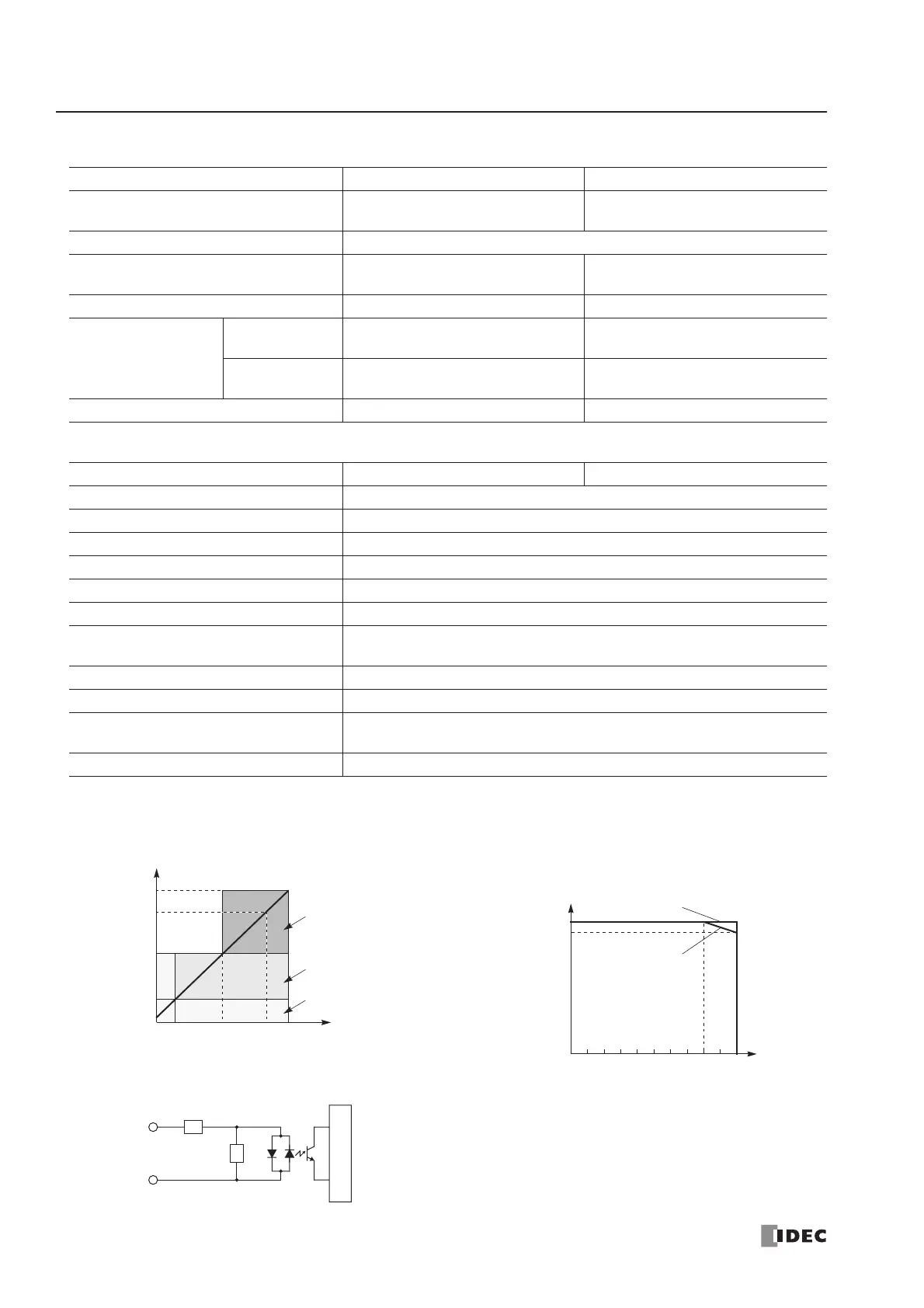
Cable Length 3m (9.84 ft.) in compliance with electromagnetic immunity
neously along line (1).
(2).
simultaneously at 55°C, input voltage 28.8V DC.