IDEC SmartRelay functions
140 IDEC SmartRelay Manual
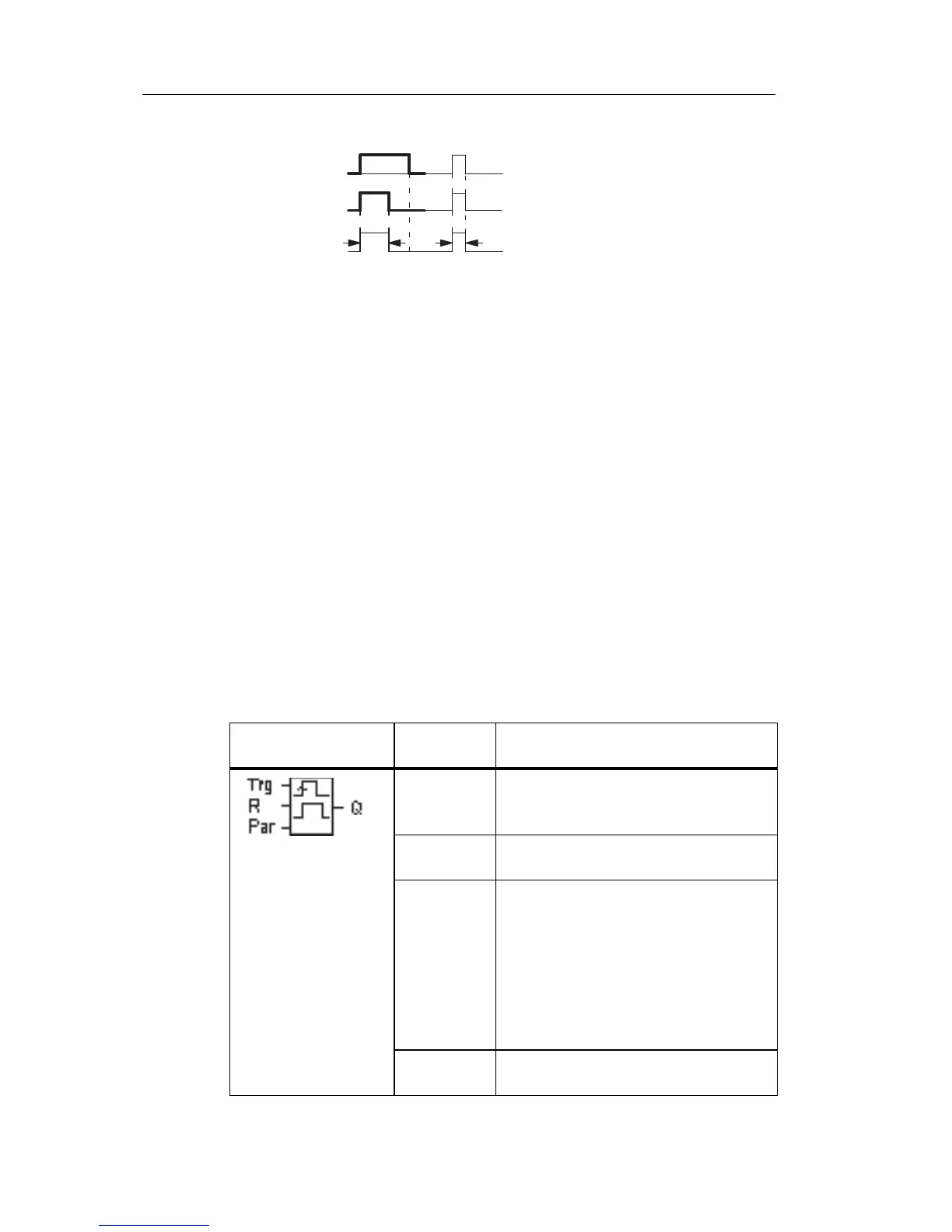
Timing diagram
Functional description
A 0 to 1 transition at input Trg sets the output, and triggers a
time T
a
during which the output remains set.
Output Q is reset to lo (pulse output) when
T
a
reaches the
value preset at T (T
a
= T).
The output is immediately reset if there is a 1 to 0 transition
at input Trg
before the specified time has expired.
If retentivity is not set, output Q and the expired time are
reset after a power failure.
4.4.6 Edge-triggered interval time-delay relay
Short description
An input pulse generates a preset number of output pulses
with a defined
pulse/pause ratio (retriggerable), after a
configured delay time has expired.
Symbol in IDEC
SmartRelay
Wiring Description
Input Trg A signal at input Trg (Trigger) triggers
the times for the edge-triggered
interval time-delay relay.
Input R A signal at input R resets the current
time (T
a
) and the output.
Parameter The interpulse width T
L
and the pulse
width T
H
are configurable.
N determines the number of pulse/
pause cycles TL/TH:
Range of values: 1...9
Retentivity:
/ = No retentivity
R = The status is retentive.
Output Q Q is set after TL has expired, and
reset after TH has expired.