3
1. System Configurations
1-1 Required hardware and application software
1-2 System configuration
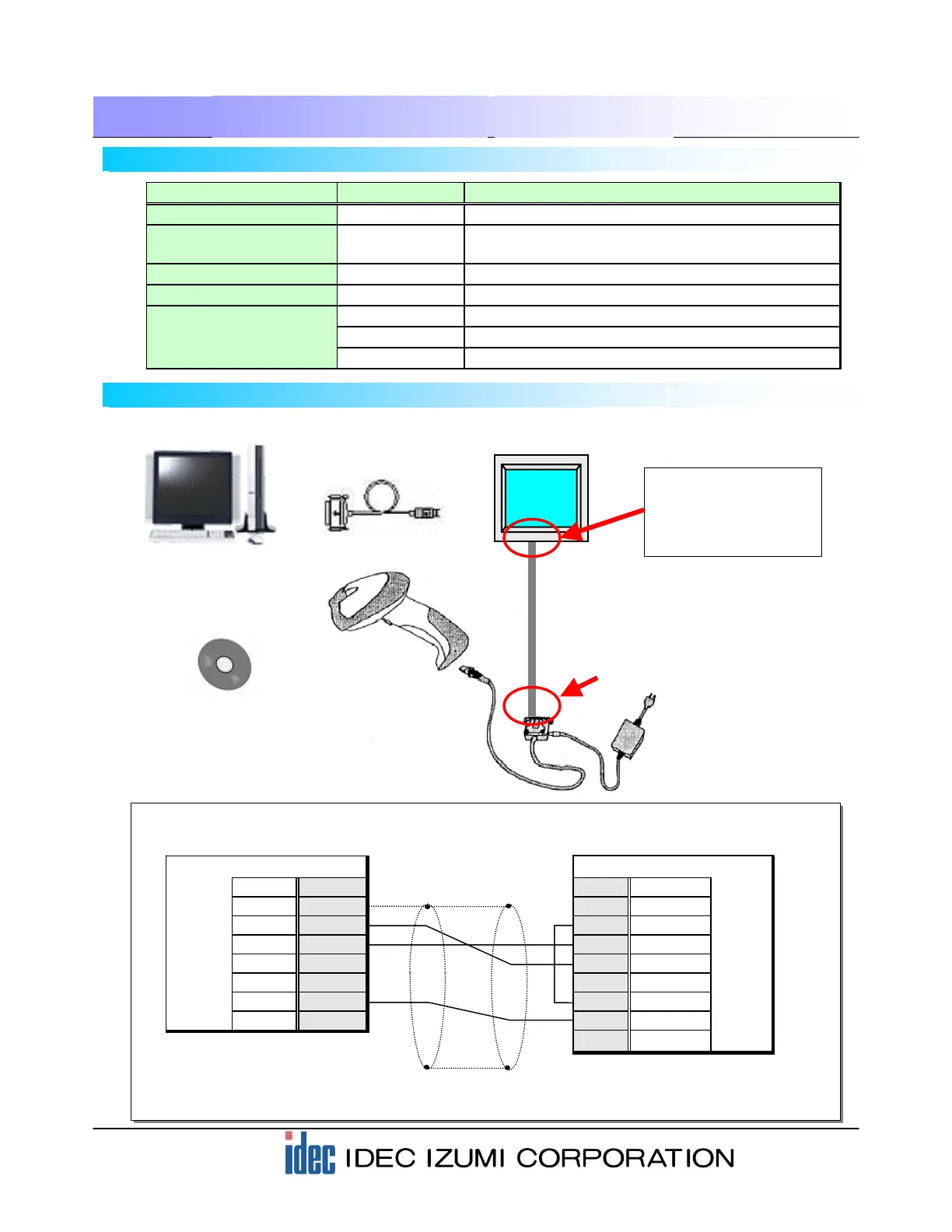
Operator Interface
Model: HG2F-SS22VF
PC
GRYPHON Barcode
Reader
Model: GRYPHON D100
RS-232C Interface Cable
Model: CAB-320
Barcode Reader AC Adapter
Model: PG5/110
User Communication Cable
Model: FC2A-KP1C
Note) The end of this cable is not
terminated. Wire the cable as shown
in the connection diagram.
* When connecting a barcode reader to the HG2F, connect the User Communication cable as shown
below. (Pins No. 2 and No. 6 are open when using the HG3F/4F.)
Barcode Reader (RS-232C) HG2F (RS-232C)
Pin No. Name Name Pin No.
1 Shield RS 1
2 TXD ER 2
3 RXD SD 3
4 RTS RD 4
5 CTS DR 5
7 GND EN 6
25 +5V SG 7
NC 8
Mini DIN 8-pin connector socket type
(HG2F/3F/4F)
D-sub 25-Pin connector socket type
Shielded wire
Connect the mini-DIN8
connector on the rear
face to SERIAL2
(Round pin).
Programming Software
“WindO/I-NV2”
Model: HG9Y-ZSS2W
Computer Link Cable
Model: FC2A-KC4C
Part Name Model Description
Operator Interface HG2F-SS22VF 5.7” STN Color LCD Type
Programming Software HG9Y-ZSS2W
HG Series Programming Software
(WindO/I-NV2 Ver. 2.7)
Computer Link Cable FC2A-KC4C Computer Link Cable 1C, RS232C Cable (3m/9.84ft. long)
User Communication Cable FC2A-KP1C User Communication Cable 1C (2.4m/7.87ft. long)
GRYPHON D100 Datalogic’s CCD Scanner for 1-D Codes
CAB-320 Datalogic’s RS 232C Interface Cable
PG5/110V Datalogic’s AC Adapter
Barcode Reader