DOC No: PN 86880 REV A
16
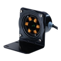
OTHER EAGLEDRIVE
ELECTRICAL CONNECTIONS
Tachometer Output
The tachometer output can be monitored using a frequency counter. The
tachometer output is 0-5V square wave pulse that occurs twice per pump drive
revolution. To convert the tachometer output to rpm, multiply the output
frequency (Hz) by 30.
Inadvertent connection of the tachometer output (green) wire to
ground or the supply voltage can cause damage to the drive. If the
tachometer is not used, trim and insulate the green lead.
Forward/Reverse Operation
The direction of uid ow can be changed by connecting the orange wire to
ground. For FORWARD ow, make NO CONNECTION to the orange wire. For
REVERSE ow, connect the orange wire to GROUND.
DO NOT reverse the direction of rotation of the drive until the drive
has come to a complete stop. Reversing the direction while the drive
is still turning may damage the motor.
Inadvertent grounding of the forward/reverse (orange) wire will cause
the drive to operate in reverse. If reverse operation is not required, trim
and insulate the orange lead.
Motor/Pump performance will be dierent between FWD and REV
operating modes.
Motor Current Output
The Motor Current Output is an analog signal (from 0 to 5vdc) that is proportional
to the actual motor amps. This signal is not heavily ltered so the actual motor
phase waveform will be visible in the signal. To use this most eectively rst
measure the signal with no speed input command to determine the oset value.
The actual signal will then be according to:
Motor Current Output = (0.95 x Actual Amps) + Oset for DEMSE products
Motor Current Output = (0.63 x Amps) + Oset for DEELE products.