7
Filta-Max xpress Operator’s Guide
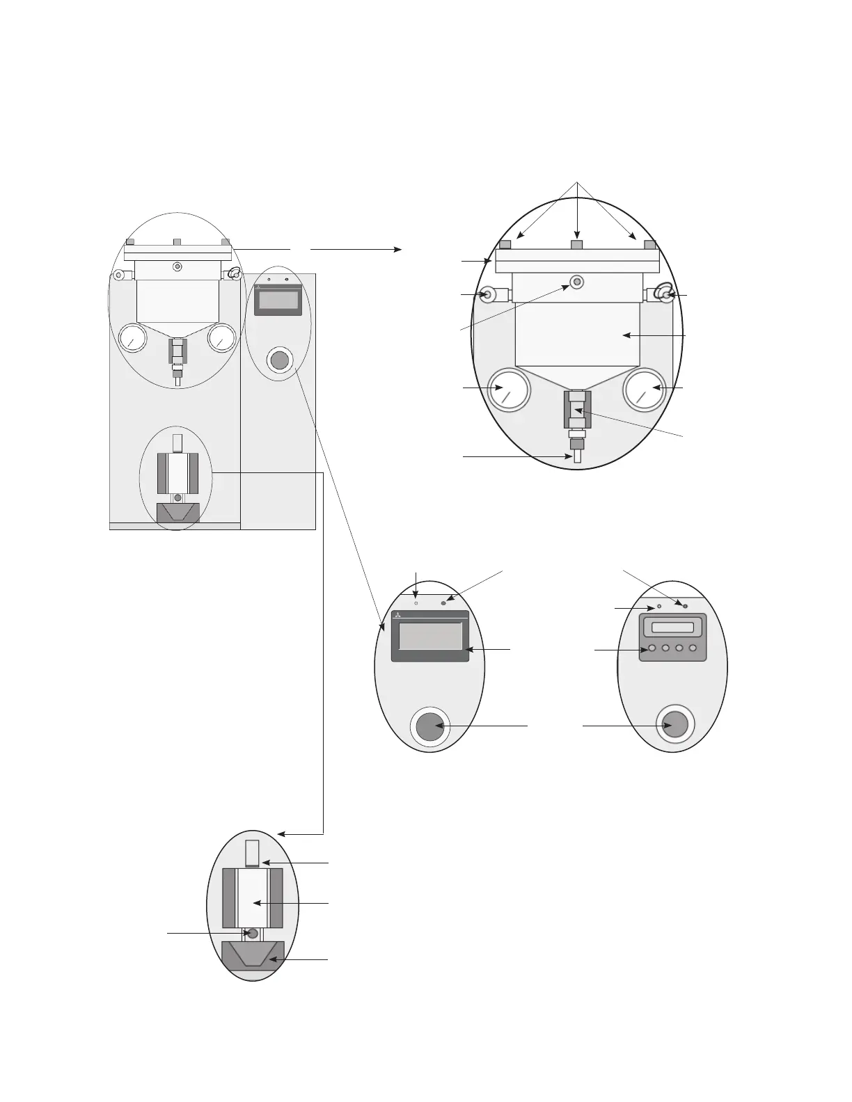
Components
Pressure Elution Station
Emergency
stop button
Green LED: power
supply indicator
Red LED:
• Steady = Machine ready
• Flashing = System fault indicator
Figure 1b. Switches and buttons
Filter Housing/outlet
diverter assembly sensor
Collection vessel
cylinder
Collection
vessel sensor
Collection vessel
holder
Figure 1c. Sensors, fittings, and vessels
Figure 1. Pressure Elution Station
without a Filter Housing and diverter
assembly
Socket head
cap screw
Pressure
chamber lid
Buffer inlet
with flow meter
Pressure
gauge fitting
High-pressure
gauge
Low-pressure
gauge
Pressure
chamber body
Air inlet with
relief valve
Pressure chamber
purge valve
Swagelok quick-
connect (QC) stem
Figure 1a. Pressure chamber and gauges
1a
1b
1c
Green LED: power
supply indicator
Touch-screen
control panel
Four-button
control panel
Control panel