10©2017 Integrated Device Technology, Inc. June 8, 2017
VersaClock
®
3S - 5P35023 Evaluation Board User Manual
Signal Termination Options
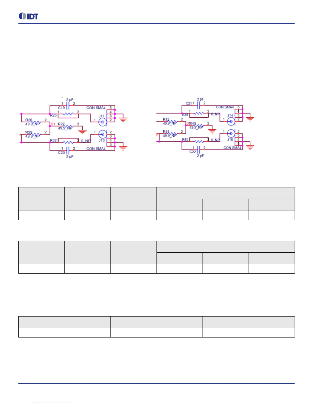
Termination options for differential output 1–2 in the evaluation board are displayed in Figure 9. The termination circuits are designed to
optionally terminate the output clocks in LVPECL, LVDS, LVCMOS and HCSL signal types by populating (or not-populating) some
resistors. DC or AC coupling of these outputs are also supported.
Table 5 and Table 6 tabulates component installations to support LVPECL, LPHCSL, LVCMOS and LVDS signal types for output 1–2,
respectively. Note that by doing so, the output signals will be measured and terminated by an oscilloscope with a 50Ω internal
termination.
Figure 9. Output Termination Options
As noted, 4-resistor network is not installed in Table 5 and Table 6 because oscilloscope with internal 50Ω termination is utilized for signal
termination and measurement. If an AC-coupled, stand-alone LVPECL output is needed (without oscilloscope connections), the 4-resistor
network needs to be installed accordingly.
Table 5. Termination Options for Differential Output 1 (DIFF_T1/C1)
Signal Type
Series Resistors:
R79, R80
Series Capacitors:
C19, C20
Resistor Network
R26, R29 R27 R25, R32
**LPHCSL 33Ω 2pF Not installed Not installed Not installed
Table 6. Termination Options for Differential Output 2 (DIFF_T2/C2)
Signal Type
Series Resistors:
R81, R82
Series Capacitors:
C21, C22
Resistor Network
R42, R44 R43 R38, R45
**LPHCSL 33Ω 2pF Not installed Not installed Not installed
Table 7. Termination for Single-ended Output 1 (SE_1)
Signal Type Series Resistors: R1 Series Capacitors: C16
*LVCMOS 33Ω Not installed