4©2017 Integrated Device Technology, Inc. June 8, 2017
VersaClock
®
3S - 5P35023 Evaluation Board User Manual
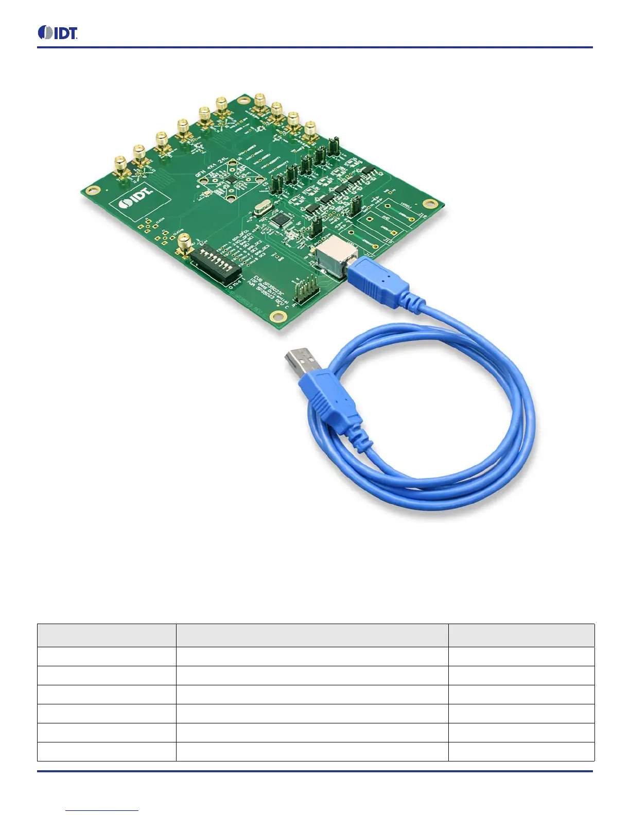
Figure 4. Connecting the Board with USB Port for Communications with Timing Commander Software
On-board Crystal
A 25MHz crystal is installed on the board and is used as a source for reference frequency.
Board Default Frequency Output
Table 2. Board Default Frequency Output
Serial Output Output Frequency
1 SE_1 (Single-ended) —
2 SE_2 (Single-ended) 48MHz
3 SE_3 (Single-ended) 60MHz
4 REF (Single-ended: Reference output) 25MHz
5 DIFF_T1/C1 (Differential output) 100MHz
6 DIFF_T2/C2 (Differential output) 100MHz