5©2017 Integrated Device Technology, Inc. June 8, 2017
VersaClock
®
3S - 5P35023 Evaluation Board User Manual
DIP Switch (SW1)
Configuration and Setup from I
2
C Port
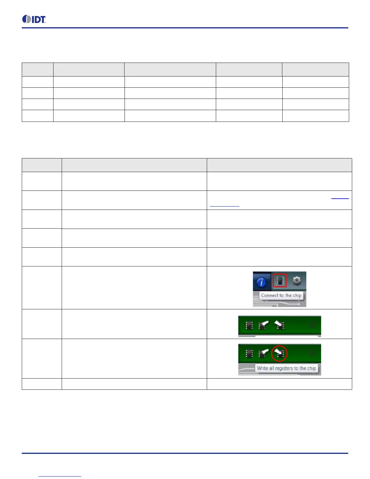
Table 3. DIP Switch (SW1)
Serial DIP Switch Pin Number DIP Switch Pin Name State Mode
A 1 SDA_DFCO Floating/Tri-state —
B 2 SCL_DFC1 Floating/Tri-state Software I
2
C
C 3, 5, 7 SMA_OE1, SMA_OE2, SMA_OE3 High or 1 —
D 4, 6, 8 OE1, OE2, OE3 High or 1 —
Table 4. Configuration and Setup from I2C Port
Step Number Step Description Comments
1 Set SCL_OFC1 Pin (DIP switch pin 2).
High or 1. The default setting from the board is pull-high
internally.
2 Launch 5P35023 Timing Commander software.
Refer to 5P35023 Timing Commander User Guide, Timing
Commander software.
3
Follow the “Getting Started Steps” in Timing Commander
software.
An I
2
C connection is established between GUI software
and VersaClock 3S device.
4
Using the Timing Commander GUI, start a new settings
file, or open a pre-optimized file.
Configure the Timing Commander software for the
required sets of outputs.
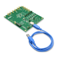
5 Connect J3 to a USB Port using the supplied I
2
C cable.
An I
2
C connection is established between GUI software
and VersaClock 3S chip.
6
Connect to the EVB by clicking on the microchip icon
located at the right of the Timing Commander.
7
Once configured, new options will be available on a green
background indicating that the EVB has successfully
connected with the board.
8
Write the setting to the device by clicking on the write all
registers to the chip option.
9 All intended outputs should be available for measurement. —