3©2017 Integrated Device Technology, Inc. June 8, 2017
VersaClock
®
3S - 5P35023 Evaluation Board User Manual
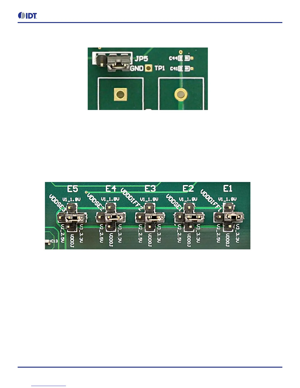
Figure 2. JP5 Jumper Position (pins 1 & 2) for the On-Board Voltage Regulators
Jumping to the pin configuration as shown will select the power source from on-board voltage regulators powered by USB.
Output Clock Voltages
Like V
DDA
and V
DD33
having two sources, each output voltage is also provided with two sources to choose from: bench power supply or
powered from USB. The selection is made by a 4-way header as shown in Figure 3 below.
The jumper can be used to select a voltage for E1, E2, E3, E4, and E5 respectively. The on-board voltage regulators powered by USB are
1.8V, 2.5V and 3.3V; V
DDOJ
is from bench power supply connecting to JP17 and JP18
Note: Each output voltage can be individually selected. Use the label on the evaluation board: E1 for V
DDDIFF1
, E2 for V
DDSE1
, E3 for
V
DDDIFF2
, E4 for V
DDSE2
and E5 for V
DDSE3
.
Figure 3. Jumper Configuration for On-board Voltage Regulators
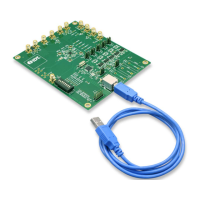
Connecting the Board
The board is connected to a PC through a USB connector for configuring and programming the device, as shown in Figure 4 below. The
USB interface will also provide +5V power supply to the board, from which on-board voltage regulators generate various voltages for the
core as well as for each output.
Note: The USB port only supports USB 2.0; USB 3.0 is not supported at this time.