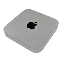
Step 18
A couple of spring-loaded T8 Torx screws secure the
oddly shaped heat sink to the processors.
In keeping with its space saving design, the fins
directing air toward the vent hole are slanted to allow
for better fan placement.
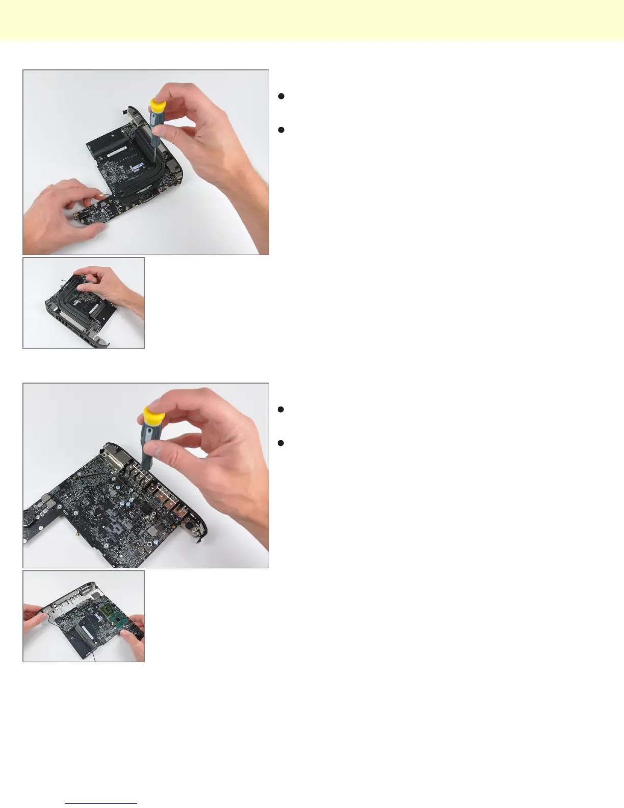
Step 19
The I/O frame is held to the logic board by a few T6
Torx screws.
The two I/O bezel antennas are more visible in this
picture. The long antenna wires are grounded
periodically along their length, presumably for better
signal transmission to the important part - the antennas
themselves.
Mac Mini Model A1347 Teardown
© 2010 iFixit — CC BY-NC-SA www.iFixit.com Page 10 of 13