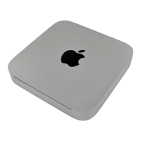
Step 14
Before completely sliding out the logic board assembly,
the power supply connector must be disconnected.
After disconnecting the power cable, the logic board
assembly slides right out.
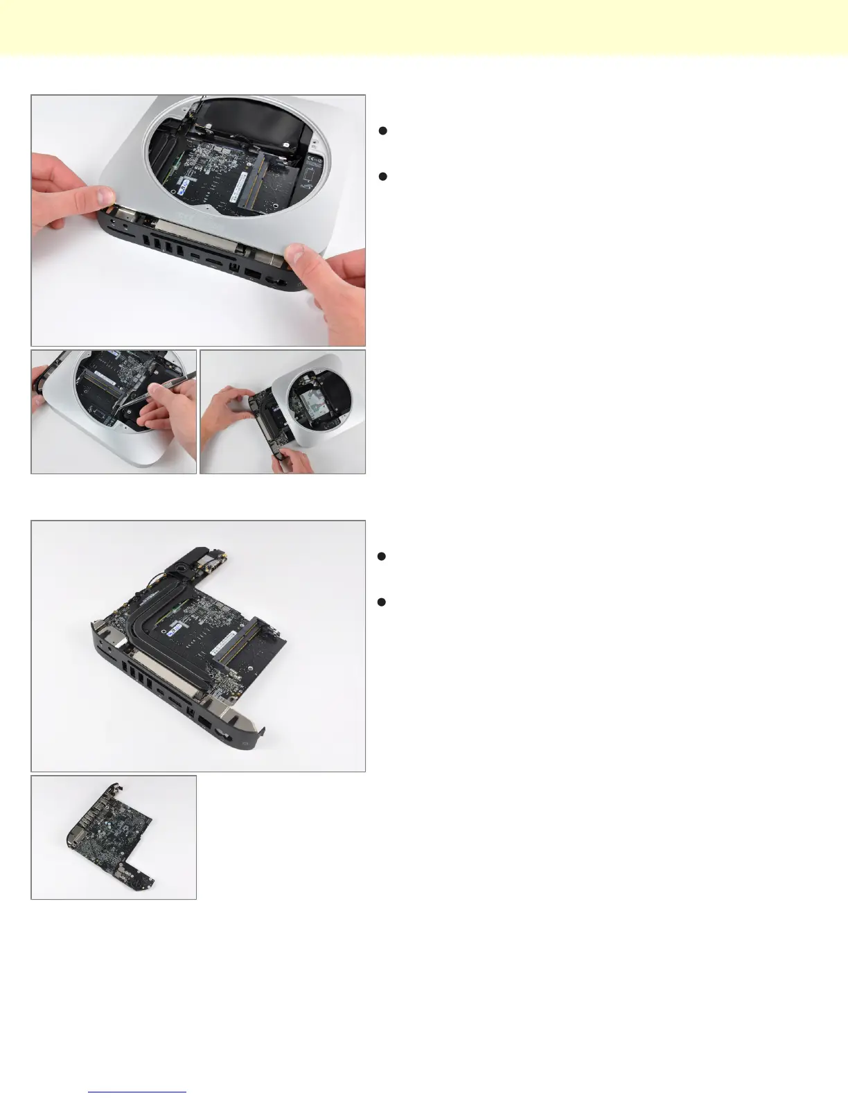
Step 15
The top and bottom of the logic board and I/O frame
assembly.
In using unibody construction, Apple had to get creative
with the placement of the antennas. Two auxiliary
antennas are the square steel components seen at
both ends of the I/O frame.
Mac Mini Model A1347 Teardown
© 2010 iFixit — CC BY-NC-SA www.iFixit.com Page 8 of 13