12
7.3 Output circuit
Last anschließen
13
3,6 A
14
23
3,6 A
24
33
3,6 A
34
77
3,6 A
78
67
3,6 A
68
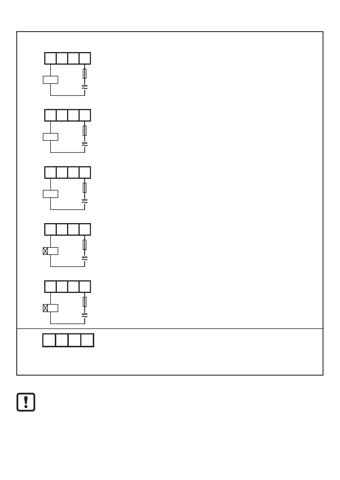
► Connect the load to be controlled to the relay outputs on
C1 (13, 14), C2 (23, 24), C3 (33, 34), C5 (67, 68) or C6
(77, 78).
Adhere to max. and min. contact rating (→ 11 Technical data).
43 44 51 52
The relay outputs C4 (43, 44 and 51, 52) provide a non
safety-related signal� The signal corresponds to that triggering
the relays at the outputs C1 (13, 14); C2 (23, 24) and C3 (33,
34).
The total current, i�e� the max� current load of all output circuits of the safety relay
(C1-C6), must not exceed 12 A.



 To Next Page