9
UK
C2 23, 24: Connection of relay output without delay, 1 x normally open
(closed when enabled)
C3 33, 34: Connection of relay output without delay, 1 x normally open
(closed when enabled)
C4 43, 44: Connection of signal output without delay, 1 x normally open
(closed when enabled)
51, 52: Connection of signal output without delay, 1 x normally closed
(open when enabled)
C5 67, 68: Connection of relay output with switch-off delay, 1 x normally open
(closed when enabled)
C6 77, 78: Connection of relay output with switch-off delay, 1 x normally open
(closed when enabled)
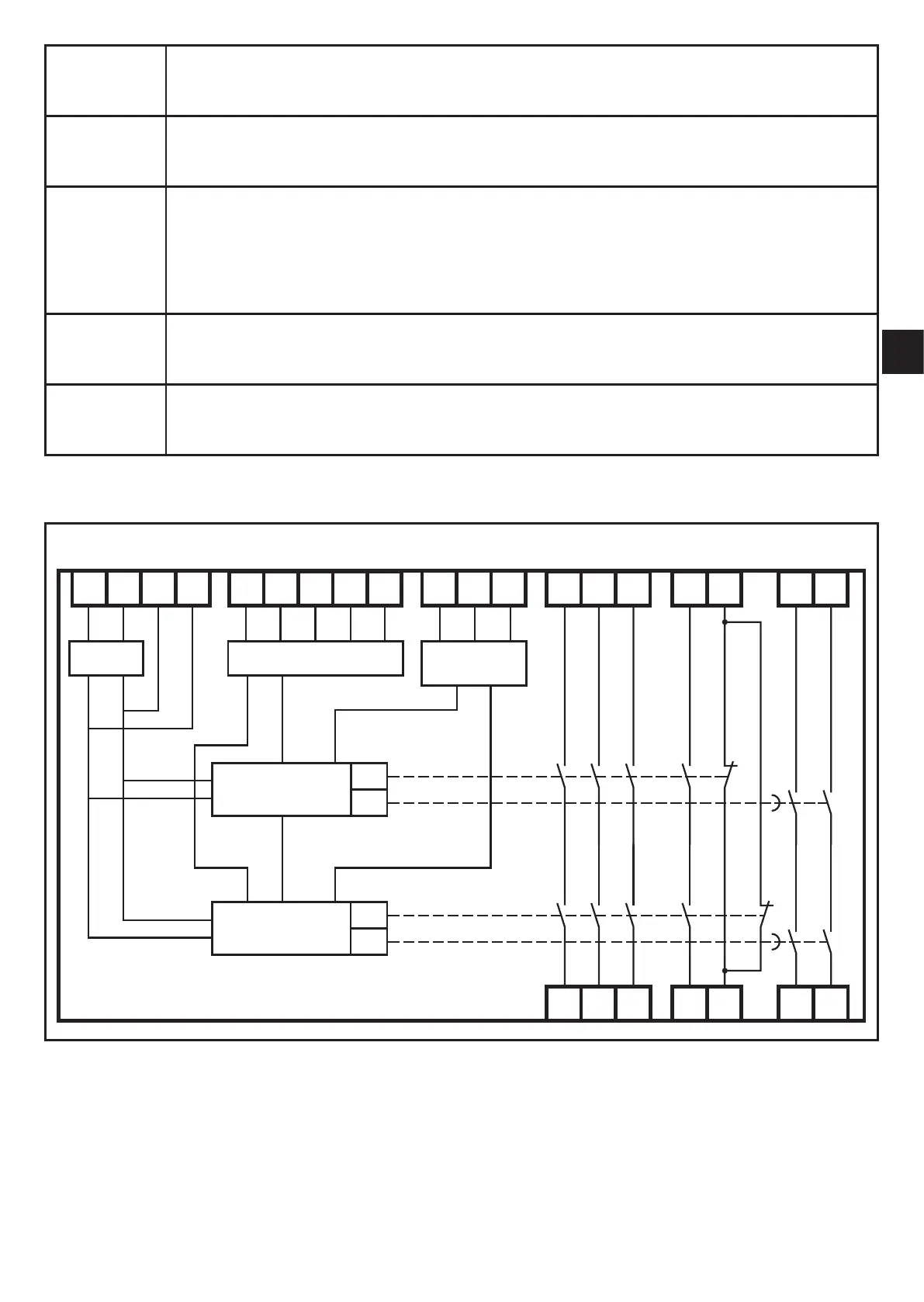
5.2 Block diagram
L+ L- Y4 Y1 S34S43 Y5 Y2 Y6 S33S44 Y7 13
14
23
24
33
34
43
44
51
52
67
68
77
78
POWER
OUTPUT
CIRCUIT
INPUT CIRCUIT
MCU 1
(CONTROLLER)
MCU 2
(CONTROLLER)
K1
K3
K2
K4