8
5 Structure and operating principle
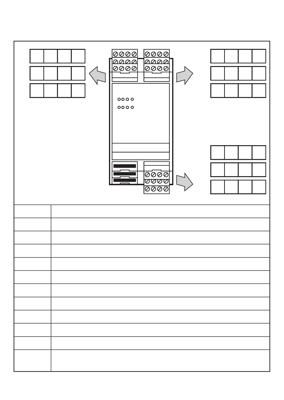
5.1 Indicators and connections
C1
C2
C3
3
2
1
C4
C5
C6
K1
E1
T1
Power
K2
E2
Fault T
Fault
S3
4
23 24
33 34
43 44 51 52
67 68
77 78
S34S43 S44
Y4 Y5 Y6 Y7
L- Y1 Y2 L+
A1 Supply voltage (L-, L+), function terminals (Y1, Y2)
A2 Y4, Y5, Y6, Y7: Operating mode selection, auxiliary output
A3 S33, S34, S43, S44: Connection for safety inputs / output
K
1 LED yellow: Triggering the relay outputs channel 1
K
2 LED yellow: Triggering the relay outputs channel 2
E
1 LED yellow: Input signal channel 1 or TE (for clocked sensor)
E
2 LED yellow: Input signal channel 2 or A (for clocked sensor)
Power LED green: Voltage supply
Fault LED red: Fault/start-up
Fault T LED red: Fault / T1
T1 LED yellow: Triggering the relay output with switch-off delay
C1 13, 14: Connection of relay output without delay, 1 x normally open
(closed when enabled)