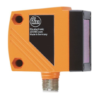
This document describes the O1D106 optical distance sensor, providing details on its functions, technical specifications, usage, and maintenance.
Function Description
The O1D106 is an optical distance sensor designed to measure distances from 1 to 75 meters on a reflector. It features background suppression for distances greater than 75 to 150 meters. The measured value is displayed on a 10-segment display, and based on configured output functions, it can generate two output signals.
Output Functions:
- Hysteresis Function (OUT1 and OUT2): This function stabilizes the switching state of the output when the measured value fluctuates around the sensing range. Set and reset points are symmetrically arranged around a selected switch point (SPx). The hysteresis is calculated based on repeatability with a safety factor of 1.5.
- Normally Open (Hno): The output switches when the object approaches and reaches the set point (A). It switches back when the object is removed and exceeds the reset point (B), where B > A.
- Normally Closed (Hnc): The set and reset points are reversed compared to Hno. The output switches off when the object approaches and switches on when the object is removed.
- Window Function (OUT1 and OUT2): This function allows monitoring a defined acceptable range.
- Normally Open (Fno): If the measured value falls between the "near" switch point (nSPx) and the "far" switch point (FSPx), the output is closed.
- Normally Closed (Fnc): If the measured value falls between the "near" switch point (nSPx) and the "far" switch point (FSPx), the output is open.
- Both window limit values (nSPx and FSPx) incorporate a switching hysteresis.
- Analogue Output Function (OUT2): The sensor can provide an analogue signal (current 4-20 mA or voltage 0-10 V) on output 2 (OUT2) that is proportional to the distance. The measuring range can be scaled by defining an analogue start point (ASP) and an analogue end point (AEP). If AEP is set before ASP, a falling edge is implemented. The minimum distance between ASP and AEP is 0.1 m; if not met, a "SIZE" error is displayed.
- Laser Switch-Off: For safety and maintenance, the laser can be temporarily switched off via an input on pin 5. A "Low" or "not connected" signal keeps the laser "On," while a "High" signal switches it "Off."
IO-Link Compatibility:
The unit features an IO-Link communication interface, requiring an IO-Link-capable module (IO-Link master) for operation. This allows direct access to sensor values and parameters, and enables parameter setting during operation. Point-to-point communication is also possible via a USB adapter cable.
- IO-Link Master Port Class A (Type A): The unit is compatible with this class.
- IO-Link Master Port Class B (Type B): Standard compatibility is not supported as pin 2 (OU2) and pin 5 (IN1) are used for manufacturer-specific functions, meaning the main and additional supply voltages are not electrically isolated. To use with Class B:
- Connect via 3 wires: Connect pins 1, 3, and 4; do not connect pins 2 and 5.
- Connect via 4 wires: Deactivate pin 2 (OU2) via IO-Link (setting OU2 = "off") and connect pins 1, 2, 3, and 4; do not connect pin 5.
Important Technical Specifications
- Measuring Range: 1 to 75 m on reflector.
- Background Suppression: > 75 to 150 m.
- Laser Protection Class: 2 (Visible laser light).
- Power/Puissance: max. ≤ 4.0 mW.
- Wavelength (λ): 650 nm.
- Pulse/Impulsion: ≤ 1.3 ns.
- Compliance: EN/IEC 60825-1: 2007 and EN/IEC 60825-1: 2014, complies with 21 CFR 1040 except for deviations pursuant to Laser Notice No. 50, dated June 2007.
- Supply Voltage: Ensure compliance with EN 50178, SELV, PELV. O1D106: cULus, Supply Class 2.
- Display: 4-digit alphanumeric display, 4 green LEDs (power, display unit), 4 yellow LEDs (switching status).
- Sampling Rate: Configurable from 1 to 33 Hz.
- Repeatability and Accuracy (on reflector):
- 33 Hz Sampling Rate:
- 1-25 m: ± 15 mm repeatability, ± 35 mm accuracy
- 30 m: ± 15 mm repeatability, ± 35 mm accuracy
- 40 m: ± 15 mm repeatability, ± 35 mm accuracy
- 50 m: ± 19 mm repeatability, ± 39 mm accuracy
- 60 m: ± 27 mm repeatability, ± 47 mm accuracy
- 75 m: ± 43 mm repeatability, ± 63 mm accuracy
- 1 Hz Sampling Rate:
- 1-75 m: ± 15 mm repeatability, ± 35 mm accuracy
- These values apply under constant ambient conditions (23°C / 960 hPa), extraneous light of max. 100 klx, and after the unit has been powered up for 10 minutes.
- Time Delay for Switching Outputs (dSx/drx): Configurable from 0 to 5 seconds in 0.1-second steps (0 = no delay).
- Fault Suppression Time (dFo): Configurable from 0 to 5 seconds (0, 0.1, 0.2, 0.5, 1, 2, 5 s).
- Laser Diode Lifetime: 50,000 hours.
Usage Features
Operating Modes:
- Run Mode: The normal operating mode after power-on. The unit performs monitoring and generates output signals based on set parameters. The display shows current distance, and yellow LEDs indicate output switching status.
- Display Mode: Allows viewing parameters and their set values without changing the operating mode. Accessed by briefly pressing [MODE/ENTER]. Parameters can be scrolled with [MODE/ENTER] and individual values displayed with [SET]. The unit returns to Run mode after 15 seconds of inactivity.
- Object Reflectivity Mode: Accessed by pressing [SET] in Run mode. Displays an orientation value for signal strength (e.g., +100 for max. signal strength and full repeatability; +020 for decreasing signal strength and restricted repeatability).
- Programming Mode: Used for setting parameter values.
Parameter Setting:
- General Procedure:
- Select the parameter using [MODE/ENTER].
- Set the parameter value: Press and hold [SET] until the value flashes. Increment by pressing [SET] once, or scroll continuously by holding [SET]. To decrease, let the display cycle to the maximum and then it will restart at the minimum.
- Confirm with [MODE/ENTER].
- Electronic Lock: The unit can be locked to prevent unintentional settings.
- Locking: In Run mode, press and hold [MODE/ENTER] + [SET] until "Loc" is displayed.
- Unlocking: Press and hold [MODE/ENTER] + [SET] until "uLoc" is displayed.
- Timeout: If no button is pressed for 15 seconds during parameter setting, the unit returns to Run mode with unchanged values.
Configuration of Basic Settings:
- Display Unit (Uni): Select [m] or [feet]. This should be set before defining parameter values to avoid rounding errors.
- Display Setting (diS): Choose from 7 settings for measured value update rates (50 ms, 200 ms, 600 ms), rotated displays, or "OFF" (display deactivated in Run mode, but LEDs remain active).
- Output Configuration (OU1/OU2): Select switching functions (Hno, Hnc, Fno, Fnc) or analogue signals (I, U for OUT2).
- Switch Point Setting (SP1/SP2, nSP1/FSP1, nSP2/FSP2): Define limit values for hysteresis and window functions.
- Analogue Range Scaling (ASP/AEP): Set the start and end points for the analogue output.
- Teach Mode (TEAC):
- Sampling Rate (rATE): Set the time after which a new measurement result is provided.
- Repeatability (rEPr): Set the desired repeatability. The unit will calculate the corresponding sampling rate.
- Extended Functions (EF):
- Time Delay for Switching Outputs (dSx/drx): Configure switch-on and switch-off delays.
- Fault Suppression Time (dFo): Suppresses short-term saturation of the measuring element (e.g., from direct reflection or strong brightness fluctuations). During this delay, the last valid value is displayed, and outputs remain unchanged. This also suppresses "too much light" and "not enough light" errors.
- Reset to Factory Setting (rES): Resets all parameters to their default values.
- Software Version Number (SW): Displays the current software version.
Fault Indication:
The display provides specific error messages:
- [++]: Too much light (e.g., reflective surface).
- [--]: Too little light, no object.
- [nEAr]: Object to be measured outside the measuring range < 0.2 m.
- [FAr]: Object to be measured outside the measuring range > 3.5 m.
- [Errp]: Plausibility error (e.g., object too fast).
- [LOFF]: Laser switched off.
- [SC1]: Short circuit in switching output 1.
- [SC2]: Short circuit in switching output 2.
- [SC]: Short circuit in all switching outputs.
Maintenance Features
- Repair: Faulty sensors must only be repaired by the manufacturer.
- Cleaning: Keep the front lens of the sensor free from soiling.
- Disposal: After use, dispose of the unit in an environmentally friendly way in accordance with applicable national regulations.