7
UK
5 Electrical connection
The device must be connected by a qualified electrician�
The national and international regulations for the installation of electrical
equipment must be adhered to�
Voltage supply according to SELV, PELV
For use in USA and Canada: voltage supply to class 2
► Disconnect power�
► Connect the cable with the M12 connector of the unit�
Tightening torque max� 0�4 Nm�
Observe the maximum tightening torque of the connection cable�
5.1 IO-Link connection
The IO-Link port must be connected according to the IO-Link specification�
5.2 Pin connection
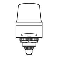
5.2.1 IO-Link mode
M12 connector, 5 poles, A-coded
(4 x 0.34 mm² / AWG 22)
1: V+
2: not connected
3: 0V
4: IO-Link
5: not connected
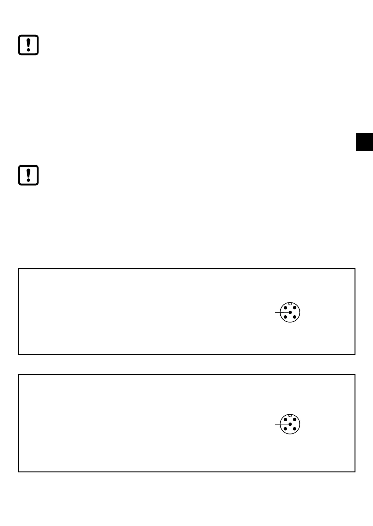
5.2.2 Standard mode
M12 connector, 5 poles, A-coded
(4 x 0.34 mm² / AWG 22)
1: LED-a (RGB red)
2: LED-b (RGB green)
3: GND
4: Feedback button (only DV21x1) /
Buzzer (only DV213x)
5: LED-c (RGB blue)