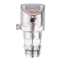
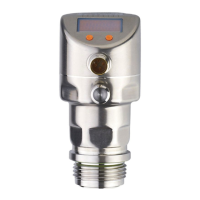
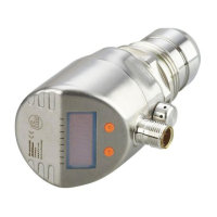
The PI17xx is an electronic pressure sensor designed to measure and monitor system pressure or the hydrostatic level and temperature in systems. It utilizes a ceramic capacitive measuring system for pressure and a medium temperature sensor on the back of the ceramic measuring cell for temperature. The device is suitable for integration into a system, with the system architect responsible for risk assessment and documentation according to legal and normative requirements.
Function Description
The PI17xx operates in SIO mode (standard input-output) or IO-Link mode. In SIO mode, the unit automatically switches to IO-Link mode when connected to an IO-Link master. IO-Link is an internationally standardized IO technology (IEC 61131-9) for communicating with sensors and actuators. It offers advantages such as noise-immune transmission of several process values, parameter setting during operation, device diagnostics (events), data storage, detection of connected units, and freely definable parameters.
The sensor provides an analogue signal proportional to the pressure, with a measuring range of 4-20 mA. The measuring range is scalable, with [ASP2] defining the measured value where the output signal is 4 mA and [AEP2] defining the measured value where the output signal is 20 mA. The minimum distance between [ASP2] and [AEP2] is 20% of the final value of the measuring range. In case of an internal error, the output signal indicates an error state (21.5 mA).
The device supports 2-wire and 3-wire operation. In 3-wire operation, it offers two possibilities for automatic changeover: switching signal for pressure limit and communication via IO-Link. The switching function can be configured for hysteresis or window operation. Hysteresis function means the output switches at a set point (SPx) and resets at a reset point (rPx). Window function means the output switches on when the measured value enters a defined window and switches off when it leaves the window.
The sensor includes an internal unit temperature sensor that provides a readable parameter for diagnostic purposes. It also features counter overpressure events (HIPC), which count how often the limit HIPS has been exceeded, and event logging (optical localisation, event history, event counter).
Important Technical Specifications
- Measuring Cell: Ceramic capacitive measuring system for pressure, medium temperature sensor for temperature.
- Output Signal: Analogue signal 4-20 mA, scalable.
- Switching Functions: Hysteresis or window function, configurable for OUT1 and OUT2.
- Overpressure Counter (HIPC): Counts overpressure events.
- Internal Temperature Sensor: Provides a readable parameter for diagnostics.
- IO-Link Interface: Standardized IO technology (IEC 61131-9) for communication and parameterization.
- Defined State in Case of Fault: If a fault is detected, the analogue output passes into a defined state (21.5 mA).
- Ventilation Diaphragm: Enables relative pressure measurement and compensates for temperature-dependent pressure fluctuations. Protected against damage by a screwed filter cover.
- Process Connection: Aseptoflex-Vario for hygienic applications, available with various sealing rings (EPDM, FKM, PEEK). Welding adapters for hygienic applications according to 3A and EHEDG.
- Display: Alphanumeric 4-digit display, LED indicators for switching status and operation.
- Parameter Setting: Via buttons on the device or IO-Link communication.
- Simulation Function: Allows simulation of pressure or error states for testing purposes.
- Factory Setting: Default parameters are provided for various settings like SP1, rP1, OU1, OU2, ASP/tASP, AEP/tAEP, etc.
Usage Features
- Customer-Specific Calibration: The sensor allows for zero-point calibration (coF) and gradient adjustment (CGA) to compensate for measured values. The calibration factor can be set in the range -5% to +5% of the final value of the measuring range (VMR).
- Installation: The unit must be installed in an environmentally friendly way. For aseptic applications, ensure no pressure is applied to the system and there is no medium in the pipe or tank before installation. Use a lubricating paste for sealing. Tighten using a spanner (35 Nm).
- Hygienic Areas (3-A and EHEDG): The device is suitable for use in hygienic areas according to 3-A and EHEDG guidelines. For 3-A, only use adapters with A-3 certification and install the unit at the lowest point of the pipe or tank. For EHEDG, ensure smooth food contact surfaces, proper CIP cleaning, and observe application limits.
- Electrical Connection: The unit must be connected by a qualified electrician. Disconnect power before connecting. Wiring diagrams are provided for 2-wire and 3-wire operation.
- Operating and Display Elements: The device features an alphanumeric display and LED indicators for status. Buttons are used for navigation and parameter setting.
- Menu Structure: A hierarchical menu structure allows access to various functions and parameters, including main menu, extended functions (level 2), and simulation (level 3).
- Parameter Setting: Parameters can be set directly on the device using the buttons. Numerical values are incremented/decremented by pressing the buttons. The unit can be locked electronically to prevent unintentional settings.
- Configuration: Display parameters (unit of measurement, update rate, orientation) and output signals (switching function, set points, window limits, analogue output scaling) can be configured.
- Service Functions: Read min/max values for system pressure and reset sensor/parameters to factory settings.
- Troubleshooting: A comprehensive troubleshooting table provides information on display warnings, errors, status LEDs, type of error, and corrective measures.
Maintenance Features
- Ventilation Diaphragm Maintenance: Avoid soiling and moisture during exchange. Clean the thread carefully and without residues. Do not damage the adhesive surface for the diaphragm. Observe the orientation of the filter cover.
- Filter Cover Replacement: If using a closed filter cover, there is no pressure compensation of the measuring cell, which can lead to measurement fluctuations caused by atmospheric pressure or internal pressure changes.
- Reset Sensor/Parameter: The sensor can be reset to factory settings. If IO-Link data storage is activated, this triggers a parameter update in the master.
- Disposal: After use, dispose of the unit in an environmentally friendly way in accordance with applicable national regulations. Ensure the unit is free from soiling, dangerous, and toxic substances for return shipment. It is not possible to repair the unit.