1.8-9
RF GENERATE
AM MODULATION
CALIBRATION
PREREQUISITES:
1-8-1
POWER
SUPPLY CALIBRATION
EOUIPMENT
REOUIRED:
1 MODULATION ANALYZER
FIGURES:
STEP
NONE
PROCEDURE
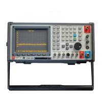
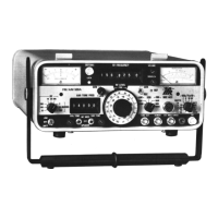
1. Apply Power
to
COM-1208.
Allow
5
minute warm-up
period.
2.
Connect
T/R
Connector
(12)
to
Modulation Analyzer lnput.
3.
Press
GEN
Test Mode Key
(3)
to access
RF
Generate Operation
Screen.
4.
Set
RF Field
to
101.0000 MHz.
5. Set Output
to
T/R
and Output
Level
to
-20
dBm.
6. Set All Modulation
Sources
to
OFF.
7.
Set
Modulation Analyzer tor 101 MHz RF.
Set
Modulation Analyzer
f
or 3
kHz
Low-Pass
Filter,300
Hz High-Pass Filter, Peak+
and
AM Measurement.
Record Residual
on
Modulation Analyzer.
8. Set GENl
Modulation Type tor AM.
9. Set
Modulation lor
30/o.
10.
Set
Format for
TONE.
With
Cursor
on
Format,
press
CONT Soft Function Key F2.
11.
Set
Tone Freq
for 1000.0 Hz.
12.
Set Shape
to SttVE.
13.
Verify Modulation Analyzer reads
30%
Modulation
(t6o/o
+
residual
[Step
7]).
lf not,
go
to
Step
21.
14.
Set Modulation
to 50o/o.
15. Verify Modulation Analyzer reads
50% Modulation
(t6%
+
residual
[Step
7]). lf not,
go
to
Step
21.
16.
Set
Modulation
lo
70%.
17. Verify Modulation
Analyzer reads 70% Modulation
(t6%
+
residual
[Step
7]). lf not,
go
to
Step
21.
18.
Set
Modulation
to 90/".
19.
Verify Modulation Analyzer reads
90%
Modulation
(t6%
+
residual
[Step
7]). lf not,
go
to
Steo
21.
1-23
1-8-9
RF
GENERATE
AM
MODULATION
CALIBRATION
PREREQUISITES:
1-8-1
POWER
SUPPLY
CALIBRATION
EQUIPMENT
REQUIRED:
MODULATION
ANALYZER
FIGURES:
NONE
STEP
PROCEDURE
1.
Apply
Power
to
COM-120B.
Allow
5
minute
warm-up
period.
2.
Connect
T/R
Connector
(12)
to
Modulation
Analyzer
Input.
3.
Press
GEN
Test
Mode
Key
(3)
to
access
RF
Generate
Operation
Screen.
4.
Set
RF
Field
to
101.0000
MHz.
5.
Set
Output
to
TIR
and
Output
Level
to
-20
dSm.
6.
Set
All
Modulation
Sources
to
OFF.
7.
Set
Modulation
Analyzer
for
101
MHz
RF.
Set
Modulation
Analyzer
for
3
kHz
Low-Pass
Filter,
300
Hz
High-Pass
Filter,
Peak+
and
AM
Measurement.
Record
Residual
on
Modulation
Analyzer.
8.
Set
GEN
1
Modulation
Type
for
AM.
9.
Set
Modulation
for
30%.
10.
Set
Format
for
TONE.
With
Cursor
on
Format,
press
CONT
Soft
Function
Key
F2.
11.
Set
Tone
Freq
for
1000.0
Hz.
12.
Set
Shape
to
SINE.
13.
Verify
Modulation
Analyzer
reads
30%
Modulation
(±6%
+
residual
[Step
7]).
If
not,
go
to
Step
21.
14.
Set
Modulation
to
50%.
15.
Verify
Modulation
Analyzer
reads
50%
Modulation
(±6%
+
residual
[Step
7]).
If
not,
go
to
Step
21.
16.
Set
Modulation
to
70%.
17.
Verify
Modulation
Analyzer
reads
70%
Modulation
(±6%
+
residual
[Step
7]).
If
not,
go
to
Step
21.
18.
Set
Modulation
to
90%.
19.
Verify
Modulation
Analyzer
reads
90%
Modulation
(±6%
+
residual
[Step
7]).
If
not,
go
to
Step21.
1-23
Scans by ArtekMedia © 2008