28 29
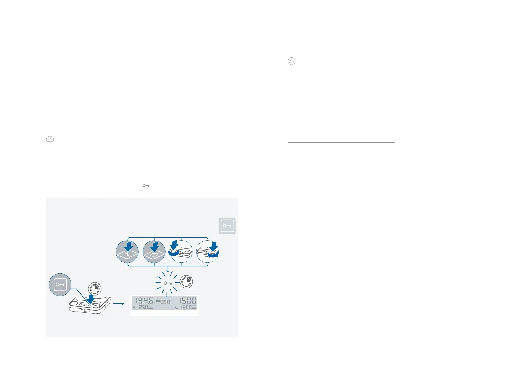
/// Lock button
› An active locking is indicated by the symbol ( )�
› Even after a power failure, the device retains the lock status�
The device can be operated by computer via an RS 232 or USB interface using the laboratory
software labworldsoft
®
�
The device software can also be updated with a PC via the RS 232 or USB port�
!
Notice!
Please comply with the system requirements together with the operating instructions and help
section included with the software�
/// USB interface:
The connected devices and their properties are detected automatically� The USB interface is
used in conjunction with software control for “remote” operation and can also be used for
software update of the device�
/// USB device drivers:
First, download the latest driver for IKA devices with USB interface from:
http://www.ika.com/ika/lws/download/usb-driver.zip
Install the driver by running the setup file� Then connect the IKA device to the PC via the USB
data cable and follow the instructions�
The data communication is via a virtual COM port�
Note: The USB driver is uncessary for Windows 10 system� Don’t install it for Windows 10
system!
/// RS 232 interface:
Configuration:
› The functions of the interface connections between the device and the automation system
are chosen from the signals specified in EIA standard RS 232 in accordance with DIN 66 020
Part 1�
› For the electrical characteristics of the interface and the allocation of signal status, standard
RS 232 applies in accordance with DIN 66 259 Part 1�
› Transmission procedure: asynchronous character transmission in start-stop mode�
› Type of transmission: full duplex�
› Character format: character representation in accordance with data format in DIN 66 022 for
start-stop mode� 1 start bit; 7 character bits; 1 parity bit (even); 1 stop bit�
› Transmission speed: 9600 bit/s�
› Data flow control: none�
› Access procedure: data transfer from the device to the computer takes place only at the
computer’s request�
/// Command syntax and format:
The following applies to the command set:
› Commands are generally sent from the computer (Leader) to the device (Follower)�
› The device sends only at the computer’s request� Even fault indications cannot be sent spon-
taneously from the device to the computer (automation system)�
› Commands are transmitted in capital letters�
› Commands and parameters including successive parameters are separated by at least one
space (Code: hex 0x20)�
› Each individual command (incl� parameters and data) and each response are terminated with
Blank CR LF (Code: hex 0x20 hex 0x0d hex 0x20 hex 0x0A) and have a maximum length of
80 characters�
Interfaces and outputs
Timer mode (count down):
› Set the desired value with the rotating / pressing knob (D)� By pressing the knob the value is
confirmed�
› Pressing the button (F) to start the timer�
› To pause the timer, press the button (F)�
› To restart the timer, press the button (F) again�
› After the timer has elapsed, the display starts flashing and a beep sounds (depending on the
menu setting)�
Counter mode (count up):
› To select the counter mode, you must set all the values to 00:00:00�
› The value is confirmed by pressing the rotating / pressing knob (D)�
› Pressing the button (F) to start the counter�
› Press the button (F) to pause the counter�
› To restart the counter, press the button (F) again�
› If the elapsed time exceeds the value of 100 hours, the display switches from hour:minute:sec-
ond mode to day:hour mode�
› If the elapsed time exceeds the value of 100 days, the counter will reset to 00:00:00�
!
Notice!
› From each state of the timer / counter, press the button (F) for 2 seconds to exit the timer /
counter�
Temp 0...310 °C Speed 0...1500 rpm
SET
SET
SAFE