2
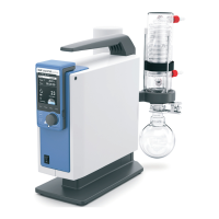
Device setup
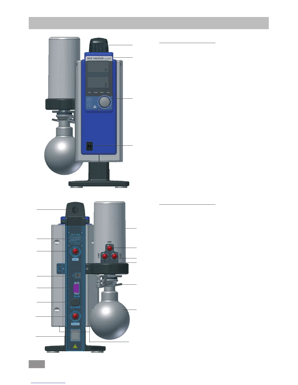
Fig. 2
5
6
7
8
9
10
11
16
13
Pos. Description
1 Handle
2 WiCo (see chapter "Operator panel and display")
3 Rotating/pressing knob
4 Main switch (on/off)
Fig. 1
Pos. Description
5 Handle securing screw
6 Fan/Ventilation slit
7 Hose connection for suction line d= 8 mm (INLET)
8 USB interface
9 RS 232 interface
10 Water Valve Connection
11 Hose connection for pressure line d= 8 mm (OUTLET)
12 Mains cable connection
13 Pressure Device
14 Hose connection for ventilation line d= 8mm
15 Hose connection for load line d= 8mm
16 Hose connection for suction line d= 8 mm (INLET)
17 Clamp
18 Receiving flask
1
2
3
4
14
12
15
17
18
6