21
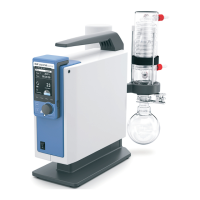
Accessories: PC 1.1 cable (device to PC)
Required for connecting the 9-pin socket to a PC.
Fig. 10
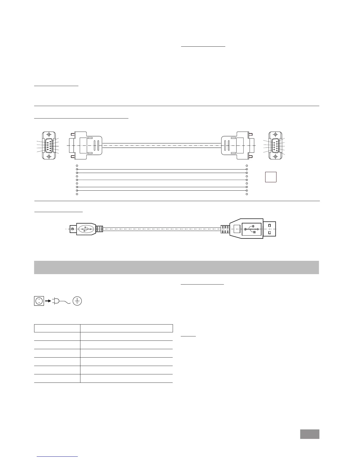
USB A - USB B cable
Required for connecting the USB interface (L) to a PC.
USB B
USB A
A
Fig. 11
Maintenance and cleaning
The device is maintenance-free. However it is subject to natural
wear and tear on parts and their statistical failure rate.
Unplug from the mains before cleaning.
Only clean the IKA device using these IKA approved cleaning
agents:
Dirt Cleaning agent
Dyes Isopropyl alcohol
Building materials Water containing detergent, isopropanol
Cosmetics Water containing detergent, isopropanol
Food Water containing detergent
Fuels Water containing detergent
Other materials Please ask IKA
• Wear protective gloves when cleaning the devices.
• Do not place electrical appliances into the cleaning agents for
cleaning purposes.
• Ensure no liquid enters the device during cleaning.
• Please consult with IKA before using any cleaning or decon-
tamination methods not specifically recommended.
Ordering spare parts
When ordering spare parts, please make sure to indicate the fol-
lowing:
• Device type
• Device manufacturing number; see rating plate
• Reference number and description of spare part; see spare
part diagram and list at www.ika.de.
Repairs
Please only send devices in for repair that have been
cleaned and are free of materials which might present
health hazards.
For this, use the “certificate of compliance” form which you
can obtain from IKA or can download a version for printing from
the IKA website www.ika.de
If your appliance requires repair, return it in its original packaging.
Storage packaging is not sucient. also use appropriate transport
packaging.
1
2 RxD
3 TxD
4
5 GND
6
7 RTS
8 CTS
1
“Watchdog” functions; monitoring of the serial data flow
If, once this function has been activated (see NAMUR commands),
there is no retransmission of the command from the computer
within the set time (“watchdog time”), the Evacuation function is
switched off in accordance with the set “watchdog” mode or is
returned to previously set target values. The data transmission may
be interrupted by, for example, a crash in the operating system,
a power failure in the PC or an issue with the connection cable
between the computer and the device.
“Watchdog” mode 1
If event WD1 should occur, the evacuation function is switched
off and WD1 Watchdog Error is displayed. Set watchdog time to
m (20- 1,500) seconds, with watchdog time echo. This command
launches the watchdog function and must be transmitted within
the set watchdog time.
“Watchdog” mode 2
If there is an interruption in data communications (longer than the
set watchdog time), the speed target value is changed to the set
WD safety speed limit. The warning PC 2 is displayed. The WD2
event can be reset with OUT_WD2@0 - this also stops the watch-
dog function.
Set watchdog time to m (20- 1,500) seconds, with watchdog time
echo. This command launches the watchdog function and must
be transmitted within the set watchdog time.