20
Interfaces and outputs
NOTE
Please comply with the system re-
quirements together with the op-
erating instructions and help sec-
tion included with the software.
The device can be operated in “Remote” mode via an RS232 or
USB interface using the laboratory software labworldsoft
®
. The RS
232 interface (M) at the back of the device is fitted with a 9-pole
SUB-D jack which can be connected to a PC. The pins are assigned
serial signals.
USB Interface
The Universal Serial Bus (USB) is a serial bus system which allows
the device to be connected to the PC. Devices that support USB
can be connected to each other whilst they are running (hot plug-
ging) and provide automatic recognition of the connected devices
and their properties.
Use the USB interface in conjunction with labworldsoft® for oper-
ation in “Remote” mode and for updating the firmware using the
“Firmware update tool”.
Installation
Before the device is connected with the PC using the USB data
cable, the USB driver must be installed.
The USB driver can be downloaded from the website.
Serial interface RS 232 (V 24)
Configuration:
• The functions of the interface circuit between the dev ice
and the automation system are a selection from the signals
specified in the EIA standard RS232 as per DIN 66020 Part 1.
• Standard RS 232, corresponding to DIN 66259 Part 1 is valid
for the electric characteristics of the interface circuits and as-
signment of signal states.
• Transmission process: Asynchronous character transmission
in start-stop operation.
• Transmission type: Full duplex.
• Character format: Character composition according to data
format in DIN 66022 for start-stop operation. 1 start bit, 7
character bits, 1 parity bit (even), 1 stop bit.
• Transmission speed: 9600 Bits/s.
• Data flow control: none
• Access method: Data transmission from the device to the
computer only occurs after a request from the computer.
Command syntax and format
The following points should be noted for the instruction set:
• Commands are generally sent from the computer (master) to
the device (slave).
• The device only responds to requests from the computer.
Even error messages are not send spontaneously from the
device to the computer (automation system).
• The commands are transmitted in captial letters.
• Commands and parameters, as well as consecutive parame-
ters, must be separated by at least one space (code: hex 0x20
).
• Each individual command (including parameters and data)
and all responses are completed with CRLF (code: hex 0x20
hex 0x0d hex 0x0A) and can have a maximum length of 50
characters.
• The dot is used for decimal separators in a floating-point val-
ue (code: hex 0x2E).
The details given above generally comply with the recommen-
dations of NAMUR (NAMUR recommendations for the design of
electrical plug-in connectors for analogue and digital signals in
laboratory MSR devices. Rev. 1.1).
The NAMUR commands and the additional IKA specific commands
are only used as low-level commands for communication between the
device and the PC. With an appropriate terminal or communication
program, these commands can be transmitted directly to the device.
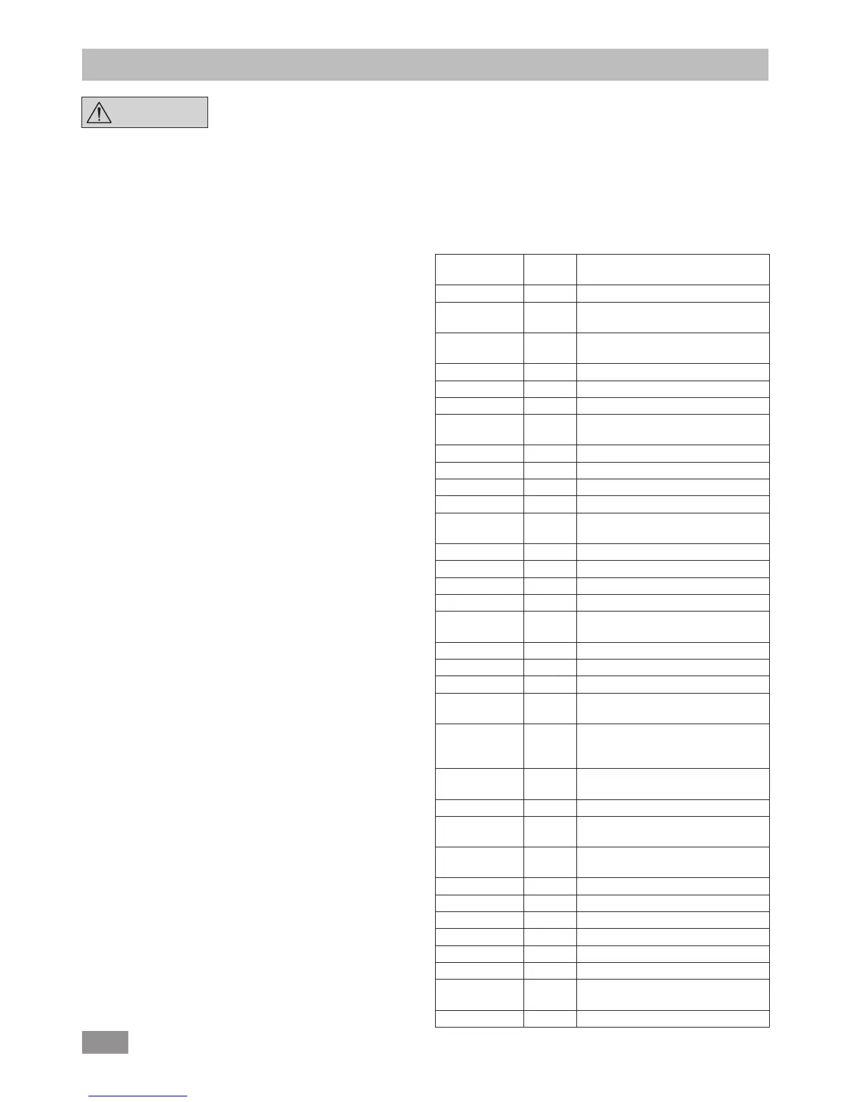
NAMUR commands Function
Command
Firmware
Version
Description
IN_PARA1 0.0.020 Return the actual values
OUT_PARA1 0.0.020 Set the set values for the pump
control
OUT_PARA2 0.0.020 Set the set values for Bluetooth
connection
OUT_STATUS 0.0.020 Send the actual device status
IN_STATUS 0.0.020 Reads the status of a device
IN_VERSION 0.0.020 Read the version of the firmware
IN_DATE 0.0.020 Read the release date of the display/
logic firmware
IN_NAME 0.0.020 Read the name of the device
IN_DEVICE 0.0.020 Read the device type.
IN_ADDRESS 0.0.020 Read mac address of Wico.
IN_PARING 0.0.020 Read paired mac address of station.
OUT_ADDRESS 0.0.020 Write new paired mac addresses of
both station and Wico.
IN_SP_66 0.0.020 Reads the set pressure value
OUT_SP_66 0.0.020 Sets set point pressure value
IN_PV_66 0.0.020 Reads the actual pressure value
IN_MODE_66 0.0.020 Reads the evacuating mode
OUT_
MODE_66
0.0.020 Sets the evacuating mode
IN_ERROR 0.0.020 Reads error state
OUT_ERROR 0.0.020 Test Error. Sends out error code
IN_BT_NAME 0.0.020 Reads Bluetooth Device Name
IN_CUSTOM_
DEVICE_NAME
0.0.020 Reads custom device name
OUT_CUS-
TOM_DEVICE_
NAME
0.0.020 Sets custom device name
IN_WD1@ 0.0.020 Reads communication watchdog
time
OUT_WD1@ 0.0.020 Sets communication watchdog time
OUT_WD2@ 0.0.020 Set PC communication watchdog
time 2
OUT_SP_41 n
(0 -100 %)
0.0.020 Set the PC safety pump rate
OUT_SP_42 0.0.020 Set the PC safety pressure
RESET 0.0.020 Switch to normal operating mode
START_66 0.0.020 Starts the measurement
STOP_66 0.0.020 Stops the measurement
ENTER_IAP 0.0.020 Starts IAP mode
CALIB_66 0.0.020 It is used to calibrate vacuum.
IN_CALIB_66 0.0.020 It is used to read vacuum calibration
values
OUT_CALIB_66 0.0.020 It is used to calibrate vacuum.
 Loading...