imc CRONOS-PL/-SL/compact - Getting Started, Version 5 R 7 - 2018-06-28© 2018 imc Meßsysteme GmbH
16 Start of operation with the Hardware
Isolated power inputs avoids ground loops in distributed topologies
With stationary installations and the use of (already isolated) AC/DC adapters, any system ground
differentials between the device and the central or local power supplies may not be relevant. The big
issue in such a case, in contrast to mobile, in-vehicle applications, is from where to obtain a reliable
ground voltage. Since it is convenient to use the AC power supply’s protection ground line as the ground
voltage, the LEMO-terminated AC/DC adapters for imc measurement devices are designed so that the
protection ground line is connected all the way through to the LEMO connector’s housing, thus securing
the device’s voltage level to protection ground. Additionally, in the AC/DC-adapter’s LEMO-terminal (not
the device’s LEMO-socket!), the reference ground of the power adapter is connected with the housing’s
(CHASSIS) protection ground: Since the AC/DC power adapter is already isolating, as is the power input,
this supply voltage’s reference would not initially be defined and can be set arbitrarily. In particular for
reasons of suppressing HF (high-frequency) interference signals stemming from the AC/DC switching
power adapter, direct grounding is normally advisable.
2.6 Shielding
Also, all signal leads to the device must be shielded and the shielding grounded (electric contact between
the shielding and the plug housing "CHASSIS").
To avoid compensation currents, always connect the shielding to one side (potential) only.If the imc
DSUB block screw terminal plug is used, the shielding should be connected to the pull-relief clamp on the
cable bushing. This part of the conductor-coated plastic plug housing has electrical contact to the device's
housing, just as Terminals 15 and 16 (labeled: "CHASSIS", to the left and right of the imc-plug cable
bushing) do; but is preferable to the "CHASSIS" terminals for optimum shielding.
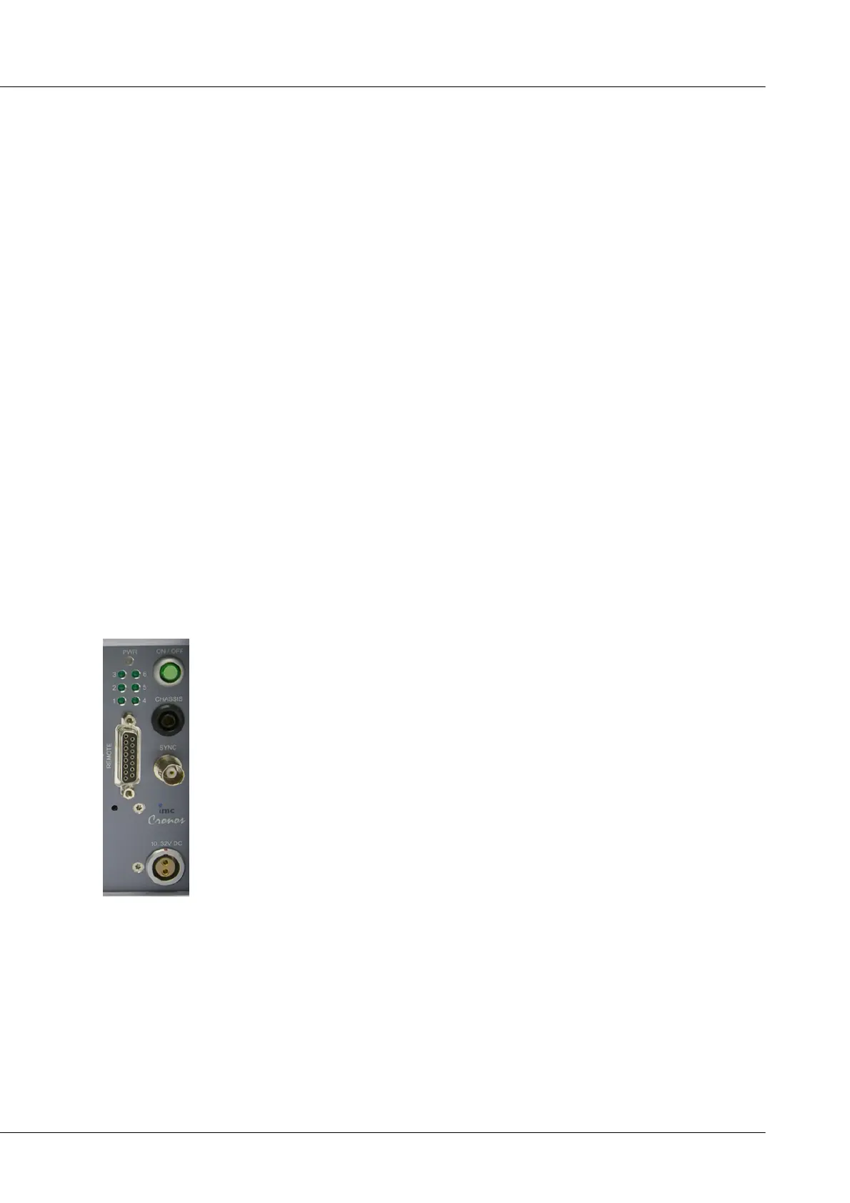
2.7 Main switch
Switch ON
The device's main switch is a power-on button with a built-in "POWER"-LED which
must be pressed down for approx. 1 sec. to achieve activation, indicated by the
"POWER"-LED flashing. If the device boots correctly, three short beep-tones are
emitted.
Switch OFF
To switch the device off, press the power-on button again down for approx. 1 sec,
what will cause a constant blinking of the "POWER"-LED. This causes the device to not
be deactivated abruptly during a running measurement. Instead, any files on the
internal hard drive involved are closed before the device switches off by itself. This
process takes up to 10 sec. Holding the power-on button down is not necessary!
If no measurement is currently running, it takes only approx. 1second for the device to
be deactivated.