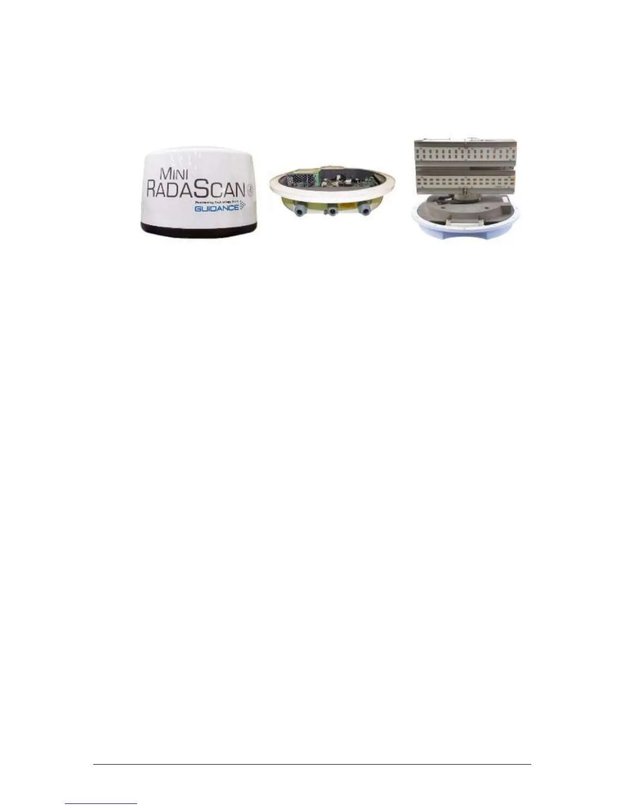
There are three main modules in the sensor.
The rotor includes:
receive (Rx) and transmit (Tx) antenna arrays;
transceiver connected to the antenna arrays;
main DSP circuit board which analyses the output from the transceiver.
The chassis includes:
belt drive, motor and encoder;
bearing, heating element and slipring;
hinge to facilitate access to the elements in the base.
The base and dome assembly includes:
gasket protecting internal elements;
small observation hatch (which includes its own seal);
power supply;
vacuum fluorescent display (VFD);
mounting holes and pressure vent;
I/O for the DP system and the dashboard.
The radar dome is attached to the base by fixing screws while the gasket ensures a tight seal.
The assembly and disassembly of the dome should only be carried out by trained personnel as it may
compromise the seal and cause damage to the sensor electronics.
The antenna arrays have been designed specifically to optimise the radar beam shape for most
applications; specifically the elevation pattern is wider than the azimuth pattern to allow the system to
cope with the pitch and roll of a vessel, and to ensure good bearing accuracy.
7.1.1 VFD – Status Display
The sensor is equipped with a display for diagnostics and fault finding purposes. In particular,
it offers a convenient way for the installer to read the network IP address and the current fault
conditions when the dashboard is unable to initiate a connection to the sensor.