20 IMCA M 229
When blending measurements from a local position reference sensor with those from GPS, it
is best to calculate the weight for the range and bearing components of the measurement
separately. This applies whether weights are assigned on the strength of an a priori
measurement noise model or in response to the observed variation of measurements.
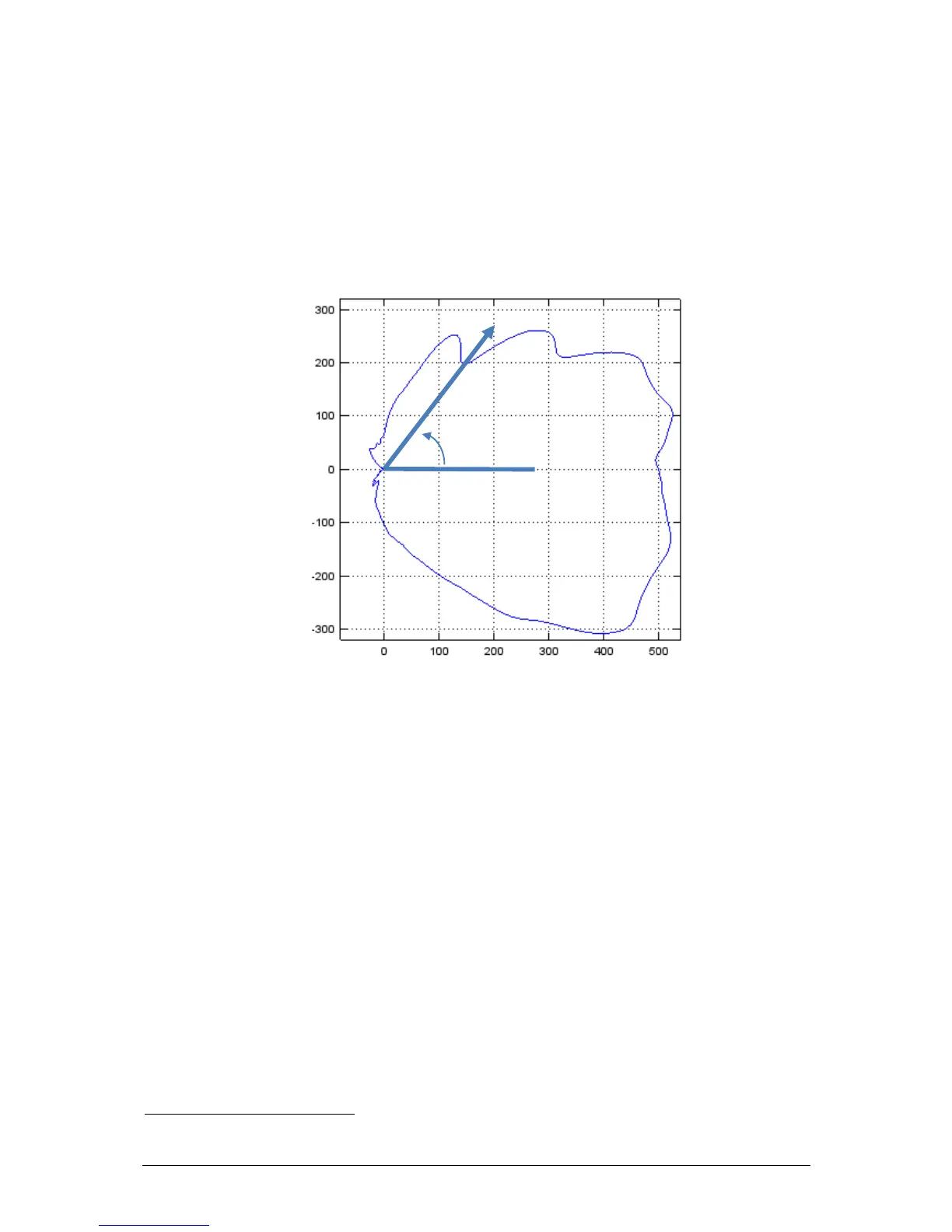
11.3 Responder Angle of Incidence
We get the maximum signal power at the sensor when the responder is facing directly towards the
sensor. The signal level falls off as the responder is pointed away from the sensor. This is illustrated in
the following plot:
Figure 16 – Azimuth antenna pattern (x and y axis represent distance in meters)
The responder is at the origin. The contour shows the positions at which the signal power received by
the sensor is equal to that received at bore sight at 500 m.
The natural tendency for any measurement system is for the errors to increase as the signal power
decreases and Mini RadaScan is no exception. The Mini RadaScan sensor monitors the signal to noise
ratio of the reflection. When this falls below a threshold, the measurement is suppressed and the fix is
not supplied to the DP system. This threshold is set so that measurements cut out before the errors
grow much above the level seen at high signal power.
It also illustrates that when using the responder in a constant wide angle configuration (e.g. Figure 11)
the maximum range (at bore sight) may not be achieved. Nevertheless, the sensor should still deliver
good performance in close range operation.
11.4 Multi-path Accuracy
It is well known in the field of microwave radar that ground or sea reflection at very low elevation angles
produces deep nulls where the radar target disappears at particular combinations of height and
distance.
The direct signal from the target interferes with the signal reflected from the water to
produce ‘Lloyd’s mirror’ interference fringes. This phenomenon affects all microwave radars (see IMCA
M 224). An arrangement of antennas at different heights can mitigate the effect and give a signal which
is adequate throughout the operating range.
Simon Kingsley and Shaun Quegan, Multipath, Understanding radar systems, section 7.4, Feb 1999, SciTech Publishing
Active Target With Height Diversity, Patent application EP 2369366, published Sept 2011