3-1
16 - IE
INSTALLATORUSERTECHNICIAN
3
CONTROL AND MAINTENANCE
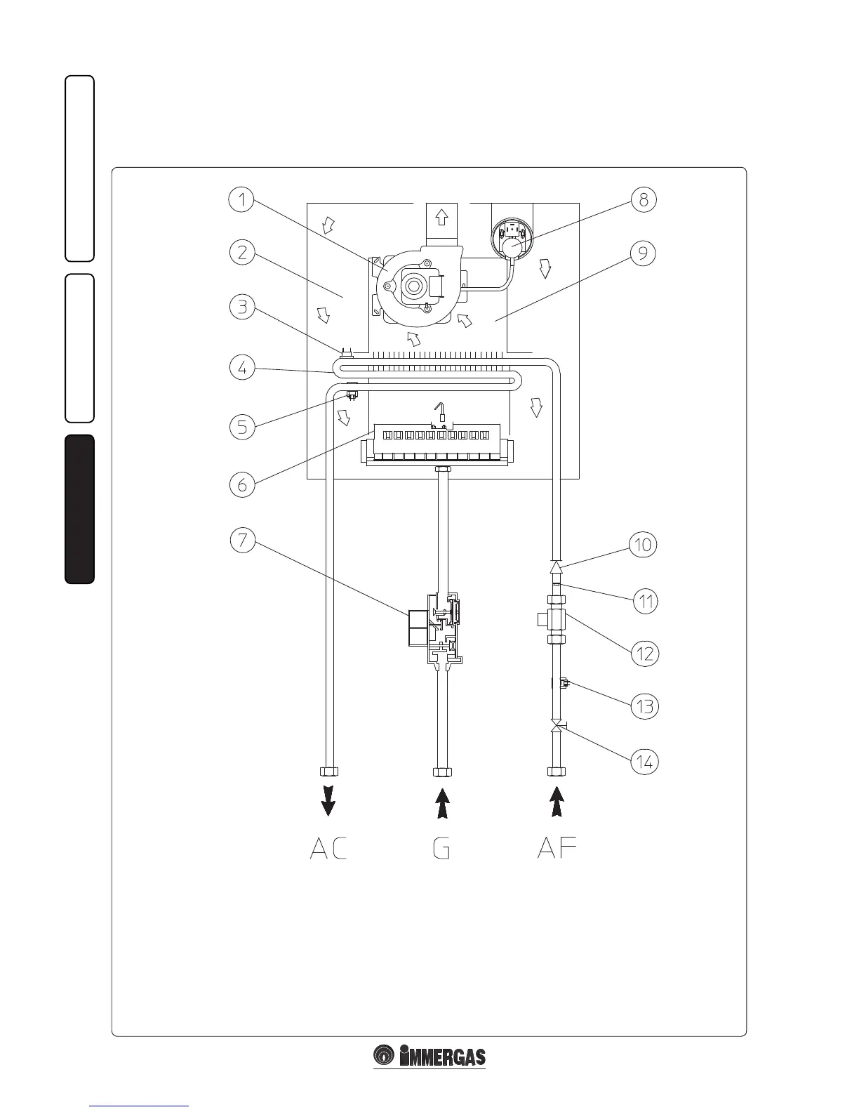
3.1 HYDRAULIC DIAGRAM.
Key:
1 - Fan
2 - Sealed chamber
3 - Safety thermostat
4 - Primary heat exchanger
5 - DHW probe (hot water output)
6 - Burner
7 - Gas valve
8 - Flue pressure switch
9 - Flue hood
10 - One-way valve
11 - Flow limiter
12 - Flow rate meter
13 - DHW probe (cold water input)
14 - Domestic hot water inlet valve
AC - Domestic hot water outlet
AF - Domestic cold water inlet
G - Gas supply