3-3
18 - IE
INSTALLATORUSERTECHNICIAN
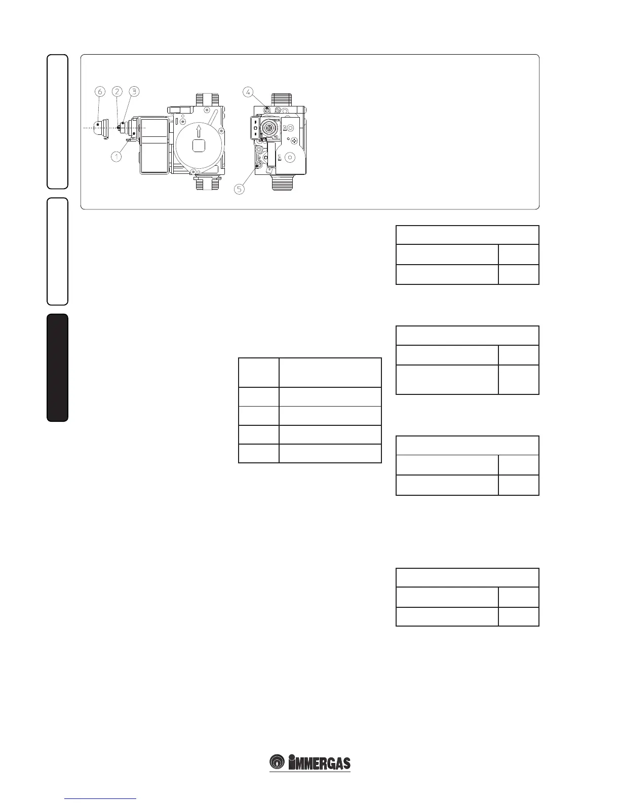
SIT 845 Gas Valve
Key:
1 - Coil
2 - Minimum power adjustment screws
3 - Maximum power adjustment screw
4 - Gas valve outlet pressure point
5 - Gas valve inlet pressure point
6 - Protection hood
3.6 POSSIBLE ADJUSTMENTS
• Adjustment of nominal heat output (Fig. 3-3).
- Turn the hot water selector knob (3 Fig. 2-1)
to the maximum functioning position;
- Open the domestic hot water cock in order to
prevent modulation intervention.
- Adjust the water heater nominal power on the
brass nut (3), keeping to the maximum pressure
values stated in the tables (Par. 3.13) depending
on the type of gas.
- By turning in a clockwise direction the heating
potential increases and in an anti-clockwise
direction it decreases.
• Adjustment of minimum heat output (Fig. 3-3).
N.B.: only proceed aer having calibrated the
nominal pressure.
Adjustment of the minimum thermal input
is obtained by operating on the cross plastic
screws (2) on the gas valve maintaining the
brass nut blocked (3);
- disconnect the power supply to the modulating
coil (just disconnect a faston); By turning the
screw in a clockwise direction, the pressure
increases, in an anti-clockwise direction it
decreases. On completion of calibration, re-
apply the power supply to the modulating
coil. e pressure to which the water heater
minimum power must be adjusted, must not
be lower than that stated in the table (Par. 3.13)
depending on the type of gas.
N.B.: to adjust the gas valve, remove the plastic
cap (6); aer adjusting, ret the cap.
3.7 PROGRAMMING THE P.C.B.
The water heater is prepared for possible
programming of several operation parameters.
By modifying these parameters as described
below, the water heater can be adapted according
to specic needs.
To access the programming phase, proceed as
follows:
- press keys (1) and (2) at the same time for
approximately 10 seconds, keeping the selector
(3) at minimum;
- using key (2), select the parameter to be
changed indicated in the following table:
List of
param-
eters
Description
P1 Solar delay timing
P2 Gas type selection
P3 Ignition power value
P4 Display lighting
- adjust the corresponding value consulting the
following tables by turning the selector (3);
- conrm the value set by pressing the Reset
button (2) for about 3 seconds.
e value ashes when it is memorised.
N.B.: aer a period of time, without touching
any keys, the operation cancels automatically.
Solar delay timing.e water heater is set to
switch-on immediately aer a request for DHW
In the case of coupling with a solar storage tank
positioned upstream from the water heater, it
is possible to compensate the distance between
the storage tank and the water heater in order
to allow the water to reach the water heater. Set
the time necessary to verify that the water is hot
enough (see par. Solar panels coupling)
Solar delay timing
Range of values which can
be set
Parameter
From 0 to 60 sec. (0 Standard
setting)
P1
Gas type selection. e setting of this function
is used to adjust the water heater in order to
function with LPG gas or Methane gas.
Gas type selection
Range of values which can
be set
Parameter
G Town gas (rst family gas)
LG (LPG) or nG (Methane)
(nG Standard setting)
P2
Ignition power value. The water heater has
electronic modulation that adapts the ignition
power according to requirement.
Ignition power value
Range of values which can
be set
Parameter
from 0 % to 50 % (35 % Stand-
ard setting)
P3
Display lighting. Establishes the display lighting
mode.
0 O: the display is always o.
1 Automatic: the display lights up when the water
heater is used.
2 On: e display is always lit up.
Display lighting
Range of values which can
be set
Parameter
0 - 1 - 2 (1 Standard setting) P4
3.8 AUTOMATIC SLOW IGNITION
FUNCTION WITH TIMED RAMP
DELIVERY.
In the ignition phase, the burner ignites at the
"ignition power value" set (P3), aer which, on
the basis of the DHW withdrawal it carries out
a gas supply increasing ramp (with pressure
values that depend on the type of gas selected)
with a pre-dened duration. is prevents every
calibration or precision adjustment of the water
heater ignition phase in any conditions of use.